Muzzle kit (noise gate diy) , how to mount IC THAT 4305 DIP 20 ?

Hi there

I first ordered the Muzzle kit and after few diy pedals with absolute satisfaction , the noise gate is the exception to not work . :( :unsure:

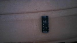
I've checked with audio probe the signal circuit and the consequence is the THAT 4305 , which I strongly suppose I've put in the wrong side on its basement....

And the questions are

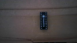
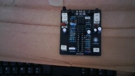
"How to mount the THAT 4305 with both brackets with each one 10 pins , with no mistake, obviously? Side 1 or 2 to the top (see pics below)?

The little curve must match with the one on the basement, I think we can be sure...

Do I need to solder the pins?

Thx for reply

Regards

Bruno

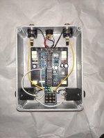
Some pics of the PCB and IC:
 

Attachments

  • That 4305 side 1.jpg
    That 4305 side 1.jpg
    288.8 KB · Views: 56
  • THAT 4305 side 2.jpg
    THAT 4305 side 2.jpg
    283.5 KB · Views: 55
  • Muzzle kit PCB .jpg
    Muzzle kit PCB .jpg
    415.8 KB · Views: 58
Last edited:
Ok so
1: here is the orientation for the IC the ⭕️ square pads are the #1 pin, these should be connected for proper orientation,
0AE16668-1FC0-4589-9A0F-BC8EA1B8A0BE.png
It looks like you have the pin headers soldered on the opposite side as needed, the “PPCB” logo is the bottom of the board and this is the side you want to solder the pin headers to.

If the circuit still does not work then further troubleshooting would be needed, the issue would probably be on the PCB and not the retrofit module.
 
If the circuit still does not work then further troubleshooting would be needed, the issue would probably be on the PCB and not the retrofit module.
Thx a lot , Paradox! :-)

So I installed it with right manner!

However , even if I've read your supposition about PCB , another doubt is the right manner to connect stereo switched jacks ( the Key SideChain ) to the other one (Passthrough) , I mean "the "switched tip" and the "tip" .

If you could bring me something to connect it without mistake?

And what about the ground?

PedalPCB-Muzzle-Classic switched tip.jpg


I see here , from Elijah-Baley:


All the components seems to be placed the same way on my PCB.

But maybe one is out of service...
 
If you have your pass through/side chain jacks wired as per the build doc it should work, if not you have other issues on the board, this is a little bit more of a complicated build and probably one of the more intermediate to advanced projects of PPCB especially if your troubleshooting skills aren’t up to that level, sometimes its good to put troublesome projects aside, move on and get a couple of finished builds under your belt then revisit the more complex one.
 
Here's the wiki page where you see what the pins are on your key jacks: PedalPCB wiki

I think there's no way you can remove the soldered pins from the THAT4305 PCB. I guess you need to buy a replacement.
 
If you have the Musikding kit maybe also check if you have a blue/red dual LED. If that's the case try to get your hands on a 5mm common cathode green/red one. The blue/red is not the correct LED and is way too bright. I replaced mine today.
 
If you have your pass through/side chain jacks wired as per the build doc it should work, if not you have other issues on the board, this is a little bit more of a complicated build and probably one of the more intermediate to advanced projects of PPCB especially if your troubleshooting skills aren’t up to that level, sometimes its good to put troublesome projects aside, move on and get a couple of finished builds under your belt then revisit the more complex one.
You know, I've built several DIY pedals (1 comp, 1 wah, 2 OD, 1 reverb ) , after mounting, first try, it worked!!! (y) ;):geek:
The logical thing you discribe is the evidence, the Muzzle kit is more complicated!
I've to go further with my "audio probe", maybe the other IC are out of service....
However I suggest some more informations to connect this thing or others, it misses in the building doc!!!! :rolleyes::unsure::unsure::unsure:
"Go fishing" on the net with forum could be avoided...
 
Here's the wiki page where you see what the pins are on your key jacks: PedalPCB wiki

I think there's no way you can remove the soldered pins from the THAT4305 PCB. I guess you need to buy a replacement.
micmac, you da man!!!! (y):sneaky::geek:
Thx so much!

The replacement of THAT thingy is in project, first I think I've to do it, after all it was maybe deficient, and reversing it on the basement made that I killed it! (n):poop:
 
If you have the Musikding kit maybe also check if you have a blue/red dual LED. If that's the case try to get your hands on a 5mm common cathode green/red one. The blue/red is not the correct LED and is way too bright. I replaced mine today.
Yes, it comes from Musikding.
They give a purple/pink LED (=if my eyes see this colour...) .
However I own a green/red LEd in my spare parts.
Roger that! ;)
 
And what about the ground? I mean the ones of the Keys.
I' ve made like @micmac example , if I see clearly what he did, he linked the sleeves of both sidechain keys .
No connexion with the ground of the PCB?
 

Attachments

  • Muzzle kit assemblage.jpg
    Muzzle kit assemblage.jpg
    426.5 KB · Views: 37
Yes that's right. I connected the slanted corners of the jacks.

Initially I had it exactly like in the PedalPCB document. But then I had lots of noise from the passthrough, I could almost not hear the guitar, only lots of noise. I read somewhere that this could happen with isolated power supplies. I have one of those.

The PedalPCB docs kind of makes a point to not connect the passthrough ground to the pedal ground. I mean PedalPCB didn't write about it, but in the picture that's how it is. Then I read on the musikding forum that you could just connect the sleeves of the passthrough, so that the guitar would get ground from the amp like that.

That seemed like a good compromise to me, so I tried it and it worked just fine. I also ran the in- and output of the pedal through the FX loop of my amp (usually I don't use it) and there was no ground loop like this either.

I read also somewhere (or maybe saw pictures of it) that some people connect (at least the key input) to pedal ground. But I didn't want to go that far.

Anyway, I guess it depends on your situation in a way. I'm no electrician :)
 
Thank you so very much, micmac. :)
So I let your example like it is in my pedal.
For the moment, I have to replace my THAT 4305 and maybe this time, the Muzzle will work! (y)
 
Hello there!
I wanted to give some news.
Finaly changed , after long time of availability of the parts, the IC That 4305 , with right plug and soldering the pins and...the Muzzle still doesn't work ....:(
That's the risk of DIY ..I wanted a cheaper noise gate and maybe the success won't come! :mad:
However, I'll do another check with my audio probe .
It's the devil if it won't work one day !!!! :devilish:
.....................................................................................
Few moment later....

It works! (y)

Fortunatly I ordered the 3 ICs as spare parts and it occurs that the LT1054 (IC1) was out of use !

So I check the noise gate in situation with no FX loop and 4 cables methode , it appears that the effect is too much delicate with Nux Cerberus, when I use clean sound , the noise gate is too present, and I'd like to not switch off the Muzzle! 😒

And when I want to separate overdrive circuit and space/modulation circuit with the Nux Cerberus , the noise gate has no reaction.:(

I'll check it with my Mesa Boogie FX loop, but with my pedal board and the Nux, it is not very handy....

...............................................................

Few moment later....

The Muzzle pedal was evaluated yesterday at the rehearsal, it works fine! No loss in the clean or OD/DIST sounds with fine adjustment of the threshold! (y)
Simply with 2 cables method with no FX Loop, it works fine and definitively this pedal will be present on my pedalboard.

If I use 4 cables method , there's too much latency! (n)

So what's the real use of the sidechain circuit? A buffer ?
 

Attachments

  • FORTIN_zuulplus_2023_2CM no FX loop.jpg
    FORTIN_zuulplus_2023_2CM no FX loop.jpg
    75.9 KB · Views: 15
  • FORTIN_zuulplus_2023_4CM no FX loop.jpg
    FORTIN_zuulplus_2023_4CM no FX loop.jpg
    80.6 KB · Views: 15
Last edited:
Back
Top