Diode Question

Strat68

Member
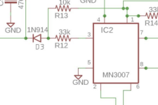
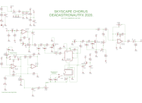
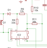
I finished building the Dead Astronaut FX Skyscape Chorus - and there is no chorus sound. Dry signal is OK, no wet signal. The volume control works. I need clarification on the schematic. I attached the full one and a snippet where the problem lives. Before I post pedal photos and the like please take a look at the snippet. The signal never enters the MN3007. It stops at the diode using an audio probe. I assume the signal should enter the IC on pin 3 right after the diode. Correct? I re-checked the diode orientation on the board and the soldering around it and it's fine. Changing the Mix setting does nothing. The diode has been replaced with no change.
Thanks all!


snippet.png full-schematic.png
 
Last edited:
No, not working. I'll go back to check parts, solder, and some voltages.

In your OP you say the signal enters the MN3007 right after the diode (D3), which (to state the obvious according to the schematic) is incorrect.

After the diode, the signal has to go through a voltage divider formed by R12 & R13, with the former being the component last seen by the signal before entering the MN3007 — ie R12.

You also mentioned the signal stops at the diode, does it get to the junction of R12 & R13 at all?

You've already replaced the diode... hhmmmm — Bad trace on the PCB? Maybe try skipping the PCB's trace and soldering the diode directly to R12/R13 (so long as you've got continuity tested for R12 to MN3007 pin 3).
Thanks. I guess I don't understand the MN3007. pin 3 is an input. The voltages around both sides of R12/R13 are ~8.4 volts and pin 3 of MN3007 is a little 0ver 8, The voltage on the cathode side of D3is a solid 8.12. Anode side is 8.42. I should not have dropped out of electrical engineering in the late 70's.
Thanks
 
I don't understand it either.

I've got zero electrical engineering experience, so I don't get why R13 goes to pin 1, which is supposed to be GND, and also connected to pin 1 is R14 33k, it's other side connected to both outputs (pins 7 & 8). I understand the principle of splitting the signal and delaying one slightly to juxtapose the delayed signal with the original = chorus... but...

Nonetheless, the Skyscape schematic is similar to other chorus schematics I looked at (such as the GPCB Mini-Me) with similar component values surrounding the BBD.

🤷‍♂️
 
I just did a quick lookup of voltage dividers and the voltage at pin 3 makes no sense. It should be between 6 & 7 volts if my arithmetic is correct. Some of the examples I saw show one resistor being tied to ground.
 
Back
Top