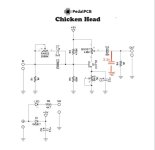
After much fiddling, confusion and disappointment, I stumbled across the idea of using a capacitor to ground via an on/off switch at the output of C4. After trying a few different values, I settled on 3n3, which perfectly rounds off the highest, unwanted frequencies without losing much level or making the circuit sound dark or veiled. I'm super happy with this very simple solution!
I'm have a question about this: C2, C7 and C4 work as high pass filters and I understand how changing the values varies the corner frequency. The 3.3n capacitor (to ground) that I've added after C4 works in the opposite way, acting as a LPF. Could someone please explain (or point me in the right direction) how/why it works this way? Does adding a cap (of roughly this this value range) to ground at the output of a pedal circuit always result in a LPF? Is there a formula or calculator that would show how the value relates to the corner frequency?
I'm have a question about this: C2, C7 and C4 work as high pass filters and I understand how changing the values varies the corner frequency. The 3.3n capacitor (to ground) that I've added after C4 works in the opposite way, acting as a LPF. Could someone please explain (or point me in the right direction) how/why it works this way? Does adding a cap (of roughly this this value range) to ground at the output of a pedal circuit always result in a LPF? Is there a formula or calculator that would show how the value relates to the corner frequency?