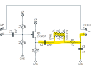
I want to use a pickup simulator in a PCP that I am making. In the past, I have used AionFx's pickup simulator. However, it has a buffer in front of it. With this circuit, I want to remove the buffer and simply have the pickup simulator. In the below picture, I highlighted the parts that I think are needed for the pickup simulator (minus the buffer), but I would appreciate someone verifying that I am correct. Thanks in advance.
my understanding is that this is kind of the point of it? (i.e. to create pickup behaviour/simulation at a point that follows a buffer/gain stage).
i.e.
- the point of the pickup simulator is to simulate pickup behaviour 'downstream'. [from the output of XFM (pin 3)]
- the buffer in front doesn't matter, because the XFM that follows is simulating the 'pickup behaviour'
(if there was a buffer after the XFM, then there would be a problem)
The main thing is simply the transformer itself, no matter how you dress it up.
For example, in Aion's Penumbra (Zeevexation Hairy Pachyderm), it ditches C2 in your Aion example in the OP.
Or...
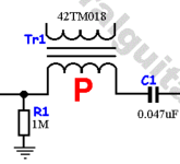
Tim Escobedo's Bronx Cheer (from GGG's schematic):
Just a PDR (R1) and an input cap (C1).
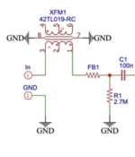
How 'bout NAEGELE AUDIO's POLARIS (Spaceman Sputnik):
@owlexifry I am actually using the Runoff Groove Splitter Blend circuit. I think you made it as a stand alone pedal. I want to integrate in into a pedal to blend two fuzz pedals together. One of the circuits is germanium, and the splitter blend has a buffer before each pedal input. I need the pickup simulator to allow the germanium fuzz to play nicely.
@Feral Feline Thanks for this information! This is perfect!
You highlighted the capacitor C2 in yellow along with the transformer and resistors, but if you completely throw out the active buffer on transistor Q3, then you don't need C2 at 100n at all. This capacitor was there only to cut off the DC voltage from the transistor output.