greypilgrim76
New member
Hi All,
I've been lurking in the forum for a while and learning a lot from all of you as I start my pedal building. I've done StewMac kits up to this point, but I recently ordered some PCBs from this site to start taking (at least some of) the training wheels off the process. I've been putting together a parts order, and everything seems to make pretty clear sense, except for the Muffinator Fuzz. the PCB doesn't appear to have the specific components identified on the board itself the way some of the others do, and on the Muffinator page, it says that the build documents are coming soon. It also says that the Muffinator is "identical to the Muffin Fuzz, with the addition of switchable diodes in each clipping stage."
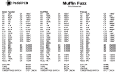
The issue I'm seeing, though, is that there are spots for components on the Muffinator PCB that aren't listed in the build doc for the Muffin Fuzz. Specifically, I'm looking at this list of components in the Muffin build doc:

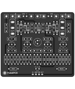
So in this document, the resistors run from R1 to R24 (plus the RLED slot), the capacitors from C1 to C15, etc. When I look at the Muffinator PCB, though, I see some discrepancies. Here's the PCB image:
 So, here are the difference I'm noting:
-No spot in the Muffinator for R24
-No spot in the Muffinator for C15
-No components listed on the Muffin sheet for D5–D8
Since I haven't done this sort of thing before, I just want to double-check how to handle these differences. For the first two, am I good to just leave those components out? For the third, do I just need to pick some diodes? If so, what are those four additional diodes doing in this circuit? Are they the two sets of switchable diodes? If so, I'm assuming D5 and D6 should be a matching pair and the same for D7 & D8? And if I'm right about that, does anyone have recommendations?
Also, there are two spots for SPDT switches. I'm assuming these are for the switchable diodes, but what does each switch do specifically? And should they be ON/ON or ON/OFF/ON?
Finally, any issues you suspect I'll run into that I don't seem to be aware of?
Sorry for the noobish questions. I tried to find as many answers as I could before posting, but there's just enough lack of clarity here that I don't want to screw it up. Any help is much appreciated! (As is all the help you've already provided without knowing it!)
Thanks!
PS--Any recommendations for this build as far as choosing between the different options in the Muffin Fuzz document? It looks like it's got slightly tailored builds for "Green Russian," "Civil War," "Triangle," "Chelsea," "Emanating Fist Dope Priest," "Bigger Muff," "SUF '75," and "SUF Mascis Muff." I'm generally familiar with some of these based on the "real" Muff pedals, but are there any that are particularly good for this build?
I've been lurking in the forum for a while and learning a lot from all of you as I start my pedal building. I've done StewMac kits up to this point, but I recently ordered some PCBs from this site to start taking (at least some of) the training wheels off the process. I've been putting together a parts order, and everything seems to make pretty clear sense, except for the Muffinator Fuzz. the PCB doesn't appear to have the specific components identified on the board itself the way some of the others do, and on the Muffinator page, it says that the build documents are coming soon. It also says that the Muffinator is "identical to the Muffin Fuzz, with the addition of switchable diodes in each clipping stage."
The issue I'm seeing, though, is that there are spots for components on the Muffinator PCB that aren't listed in the build doc for the Muffin Fuzz. Specifically, I'm looking at this list of components in the Muffin build doc:

So in this document, the resistors run from R1 to R24 (plus the RLED slot), the capacitors from C1 to C15, etc. When I look at the Muffinator PCB, though, I see some discrepancies. Here's the PCB image:
 So, here are the difference I'm noting:
-No spot in the Muffinator for R24
-No spot in the Muffinator for C15
-No components listed on the Muffin sheet for D5–D8
Since I haven't done this sort of thing before, I just want to double-check how to handle these differences. For the first two, am I good to just leave those components out? For the third, do I just need to pick some diodes? If so, what are those four additional diodes doing in this circuit? Are they the two sets of switchable diodes? If so, I'm assuming D5 and D6 should be a matching pair and the same for D7 & D8? And if I'm right about that, does anyone have recommendations?
Also, there are two spots for SPDT switches. I'm assuming these are for the switchable diodes, but what does each switch do specifically? And should they be ON/ON or ON/OFF/ON?
Finally, any issues you suspect I'll run into that I don't seem to be aware of?
Sorry for the noobish questions. I tried to find as many answers as I could before posting, but there's just enough lack of clarity here that I don't want to screw it up. Any help is much appreciated! (As is all the help you've already provided without knowing it!)
Thanks!
PS--Any recommendations for this build as far as choosing between the different options in the Muffin Fuzz document? It looks like it's got slightly tailored builds for "Green Russian," "Civil War," "Triangle," "Chelsea," "Emanating Fist Dope Priest," "Bigger Muff," "SUF '75," and "SUF Mascis Muff." I'm generally familiar with some of these based on the "real" Muff pedals, but are there any that are particularly good for this build?
