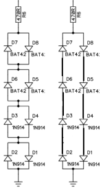
Hey folks, just looking at this "tape simulator" schematic, the original schematic is on the left, what I'm wondering is, would there be any difference compared to the version of the right?
I'm vaguely aware of the concept of diode ladders, but usually I think there are some resistors in the ladder too. Is that what I'm looking at here, or are the two examples here functionally identical?

I'm vaguely aware of the concept of diode ladders, but usually I think there are some resistors in the ladder too. Is that what I'm looking at here, or are the two examples here functionally identical?


