General capacitor questions

Audandash

Well-known member
Okay so you would think I would know this stuff since I have 10+ years pedal building experience but I just always followed the rules I learned at the beginning and never really asked questions. I am at the point now where I want to know. Could I search online? Sure. I don't really want to though since I will find information on caps for auto use and other stuff I am not going to use them for etc.. I want to know for our specific purposes, audio circuits. I also thought I would ask because it may help someone just getting started or an old timer like me in some cases. What brought me to this point is the Aionfx Amethyst (Boss DM-2). It has the standard build or you can do an Aqua Puss variant. It just has different values or components. So the question’s are about changing some of the 1uf caps to 10uf caps. Most of the 1u’s are film but when you change it to 10u its electrolytic. Please keep in mind I really want to know the answers as it pertains to audio circuits only not just in general. Here are the questions:

What is the difference in audio grade electrolytic vs standard? It’s not a tolerance thing so it must be something else. Different electrolytic solution in the cap maybe? What makes it audio grade besides a fancy colored package?

Size and price is obviously a huge factor making a 10u poly cap prohibitive. I learned you should use poly in an audio path vs electrolytic if possible. Why is that so? Is it just because an electrolytic cap won’t stay in spec as long or is it something else?

On a handful of pedalpcb boards and some others i have seen instead of using film for 1u caps mlcc caps are used. I know this is done for size but they are usually a little cheaper so why don’t more designs use them? In my experience mlcc was generally used for lower pf values and sometimes for power filtration (100nf cap thats become common). Is there soemthing wrong with using them in an audio path?

Lastly, mlcc now has a variation I see called x7r. Are the x7r the same as standard mlcc or are they different in some manner.

Thanks in advance
 
Audio grade El capw should have a lower self noise and low/almost no ESR.
I generally try to avoid them in the signal path when able, but I'm a corksniffer. if they are just decoupling caps, they can often be replaced with a large film cap. If they are also part of a filter (cap in series with signal path followed by a resistor to ground) you will need to take that into account.
Tantalum is another option.

Here's an old thread on x7r.

Aside from higher noise, their capacitance can vary with temperature and DC levels. They're basically just a smaller carbon comp, not better, just smaller.
c0g/NP0 MLCC is what you want for audio path.

There are a lot of threads here discussing caps. I would recommend searching as the community has covered this many times over.
But my stance :avoid electrolytic in the audio path. If you must, spend the money on good caps. Don't buy them on eBay/ali etc. they may be fakes and you also have no idea what their DOM is.
All that being said. It's just a pedal...
Good clean power and quality cables make a bigger impact than components. But with both an AE and EE background, I build to the standard of "best available".
Other cats here will build with x7r and tants across the board and make great sounding pedals.
Just stay clear of old caps and cheap caps. You don't have to get a $4 audio grade cap. But maybe get a 0.95 low ESR nichicon instead of the 0.11 Chinacon
 
Honestly I have never had any issues. I usually just build with what I have but was curious about the x7r’s. I like the carbon comp analogy.
 
I built an Aion Arcturus last night and it is interesting that Kevin is starting to use footprints and BOMs for large film values (e.g., 2u2 and 3u3) rather than electrolytics in the signal path. Some boards are too cramped to allow for that, but I'm a fan of at least providing that option in the PCB layout.
 
Sometimes we want the sloppy dynamics of aluminum electros. ;)
They sound fine in the BJFe Pink Purple Fuzz and Emerald Green Distortion Machine.

Leakage = noise, so if it's a high-gain pedal, I avoid aluminum electros in the audio path, at least in the first few stages.

In the majority of discrete transistor-based circuits (BMP, FF, FR, TB, RM, Electra and their derivatives, etc.), the power supply bypass caps ARE in the audio signal path.
 
Great discussion here! I dont have much to add but this little bit.

Sometimes we want the sloppy dynamics of aluminum electros. ;)
+1

Dumble frequently used X5F ceramics. Why he chose these over X7R or C0G or ?? is beyond me, but he is known for the tone of the amps he created. I believe that in some cases, as @Chuck D. Bones just alluded to, a certain amount of distortion is the desired effect. The trick is knowing which components will give this desired effect.
 
Don’t even get me started on tantalum. I have never seen much of an explanation on these over the years. If a bom says use it then I do but most of the time the bom will say, “they used it in the original so we figured it was for a reason”. lol. Good enough for me. In all fairness though my education is in biology not engineering.
 
The other thing with Electrolytics is that their capacitance performance can vary depending on where you are in their voltage rating range I think? I swear I read that somewhere, but now I don't remember where.
 
When you're designing/selecting the cap there's a tan loss angle (basically ESR) that changes over frequency applied.

Typically film caps are fine at higher frequencies but once down in the 100Hz and below, we start seeing some key differences as the ESR on those smaller film caps start impacting.

Frequency, ESR, capacitance and the tan loss angle are related through a maths formula.

If you look at WIMA caps (and I'm a bit of a WIMA fan in general because of this):
MKP10 have a tan angle of 6x10^-6 across the frequency ranges they define
MKP4 is identical to the MKP10 except the lower tan loss angle is 3x10^-6.
FKP1 has an even lower 5x10^-4 at 1Khz and 6x10^-5.

Electrolytics, even low ESR organics, are lower in the low frequencies but higher in the high frequencies. The ceramics (and multi stacked ceramics MSPP) are lower tan angle at higher frequencies but have more at lower frequencies, and a sort of half way house is the humble and often neglected Tantalum which offers high capacity but has a very nasty habit of exploding on polarity reverse or shorting when old.

What does that mean?

It means that the MKP10 has more impedance across the frequency range compared to the MKP4 which has a lower low impedance useful for guitars and the FKP1 beats them both, the kicker is the size of the FKP1. The slower the reaction (charge discharge) the less detailed and more muddy - to a point..
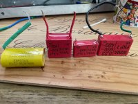
IMG_4909.jpg
That's a 10uF MPP 250Vdc, 1uF MKP10, 1uF MKP4 and a 0.22uF FKP1! Note that the rating here are for higher voltage, 630Vdc and 300Vpp AC signal. The MKP4 only has 400VDC but it's going to be in the region of 100-200VAC signal or less).

In listening tests the FKP1 is clearer (and even as a second cap bypass for bipolar MUSE electrolytics) than them all. The MKP10 is not great sounding and I'd never recommend it in the signal path, the MKP4 is quite sweet sounding and is my preferred non FKP as it's small.
In reality if you play a frequency response through all the caps then you don't really get any difference yet in a build I could hear the differences quite remarkably. I've also tried Panasonic metal foil and they don't sound good at all and I have Vishay MKT/MKP caps - but I'd not checked to hear a difference, they're in the marshall.

In the end - experiment. The nuances that work for you and your circuit is going to differ from elsewhere.
 
Last edited:
So what am getting from the responses is while in theory certain caps should be used because of certain qualities they have should make them audibly more desirable it’s like most things just try it and see what you like, lol. Anyone want to tackle what’s giving on with tantalum?
 
1754568219706.png
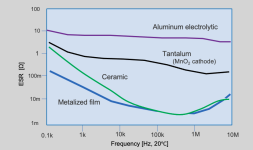
Source: https://www.aictech-inc.com/en/valuable-articles/capacitor_foundation04.html
The source of this image is very interesting, littered with mathematical witchcraft but it's understandable.
Another source would be Panasonic: https://industrial.panasonic.com/ww/ds/ss/technical/lc3

ESR/tan loss angle isn't the full picture. Remember you can parallel caps to increase current capability, this helps the poor cheap humble electrolytic do quite a bit more than a far larger equivalent capacity metalised film. Add to that the ESR needed to support audio frequencies (including their harmonics) is ultra low. Switching and clock sharp edges have more higher harmonics.
Tantalums have a better high frequency than electrolytics, without the size of ceramic/film for large capacities. If you don't use wet tantalums then they last an age too.
 
Last edited:
View attachment 100676
Source: https://www.aictech-inc.com/en/valuable-articles/capacitor_foundation04.html
The source of this image is very interesting, littered with mathematical witchcraft but it's understandable.
Another source would be Panasonic: https://industrial.panasonic.com/ww/ds/ss/technical/lc3

ESR/tan loss angle isn't the full picture. Remember you can parallel caps to increase current capability, this helps the poor cheap humble electrolytic do quite a bit more than a far larger equivalent capacity metalised film. Add to that the ESR needed to support audio frequencies (including their harmonics) is ultra low. Switching and clock sharp edges have more higher harmonics.
Tantalums have a better high frequency than electrolytics, without the size of ceramic/film for large capacities. If you don't use wet tantalums then they last an age too.
What do those 10 Ohms extra resistance across the frequency spectrum matter if all the surrounding circuitry has impedances hundreds or thousands of times higher? A 100K 1% resistor alone is going to be +/- 1000 Ohms. There's a point of diminishing returns (for audio signals at least) even if technically a certain type of capacitor might be "better".
 
Damn, I just used a slew of 1uf tants in a build due to their small size. I didn't know their ESR was so high. Maybe I should pull them out and install MLCC's instead?
 
What do those 10 Ohms extra resistance across the frequency spectrum matter if all the surrounding circuitry has impedances hundreds or thousands of times higher? A 100K 1% resistor alone is going to be +/- 1000 Ohms. There's a point of diminishing returns (for audio signals at least) even if technically a certain type of capacitor might be "better".

Agreed, in the main audio tends to be film in polyester/polyprop, electrolytic, and then the high frequency tends to be ceramics (microphonic) etc the main target for those is making the wave guides not reflect and bypassing the switching frequencies. Tantalums have fallen out of fashion but the modern ones are respectable..

Damn, I just used a slew of 1uf tants in a build due to their small size. I didn't know their ESR was so high. Maybe I should pull them out and install MLCC's instead?

That depends on the circuit. MLCC can be microphonic. All depends. Low ESR can cause instability and vice versa depending on the design.

Does it work? Yes. Don't fix it.
 
'Audio' grade is marketing nonsense to sell to schlubs, and most of the technical reasons cited are more of a justification searching for a reason type of deal. I can guarantee that NOBODY can hear a difference by changing a single cap with equivalent specifications when it's just one small part of an incredibly complex picture, something that has been backed up by thousands of blind tests at this stage.

There are reasons to use specific caps in specifics spots - tantalum is a conflict material and its mining is responsible for plenty of human misery, cheap ceramics derate with DC and can be microphonic (C0G doesn't), electros can save space over using big film caps, etc.

These are specific, quantifiable reasons that don't need justifications relying on arbitrary, nonsense terms that most audiophile bullshit relies on.
 
Last edited:
Dumble frequently used X5F ceramics. Why he chose these over X7R or C0G or ?? is beyond me, but he is known for the tone of the amps he created. I believe that in some cases, as @Chuck D. Bones just alluded to, a certain amount of distortion is the desired effect. The trick is knowing which components will give this desired effect.

Ya know, I'm kinda skeptical about this train of thought.

Cause there's really three options here.

A) the golden eared fellow specifically picked the inferior (as defined by its operation vs what one would define as an "ideal") capacitor because unicorn farts smell like the finest vintage wine corks and they have the refined pallet to be able to determine such things

B) They made an economic decision to use an inferior quality component simply because it was cheap and convenient that suited the circuit without doing extensive A/B testing.

C) They did some testing and determined that the difference was negligible and not worth the added expense of the component that behaves closer to the concept of the "ideal" capacitor.

Honestly...I'm inclined to believe that more often than not, it's either B or C.

Keep in mind...when I say "inferior" I only mean as compared other capacitor types that hew closer to the idealized concept of a capacitor. Zero ESR, Zero dielectric absorption, zero parasitic inductance...yada blah.

But there is no such thing as an ideal capacitor. Instead, we kinda pick and choose based on specific characteristics and economics. Like...if you're picking a cap for decoupling duty on an IC, a surface mount X7R is both a cheaper option than a leaded Film cap, *and a better one*. Why? You don't need any of the film cap's advantages in this scenario, and the larger size/construction/longer conductors involved introduce a greater degree of parasitic inductance.

And by "economics" I don't only mean "cost". Space is another resource that must be managed, and sometimes a smaller form factor is worth tradeoffs...and those tradeoffs may not ultimately be...eh...perceptible.

Anywho...caps. "Audio grade" caps in the small form factor, elna silmic and nichicon U...V..z.....blah blah aren't made anymore. Those were discontinued a few years back when the specific aluminum film product that they used to make their plates was...ah...discontinued? Basically, the raw material ain't made anymore, so no more silmics.

I've measured a bunch of those, and honestly, I don't think it's got anything to do with ESR. UPWs tend to have lower ESR from what I've seen.

I get the impression that it mostly had to do with marketing. Can't say for certain, but that's where I'm gonna plant my flag.

Now...having said all that: I absolutely have a stock of Teflon caps that I'm going to be using as range capacitors in wah pedals. Because I am a psychologically unwell individual who's base pathology is to hyperfocus on things that absolutely do not matter. You can call me stickman.
 
Back
Top