DEMO Stuffed Crust (176 inspired tube class A compressor)

This post contains an audio or video demo
3 videos uploading
* sine wave showing attenuation on scope
* guitar into scope showing attenuation
* guitar into amp where you can hear the difference vs hard hitting the front end of the JCM hight gain.

These are uploading and processing..

Signal generator+Scope

You can see the purple showing input, and the yellow output that's attenuated. Note that there's a little phase delay due to the decoupling caps between the stages like every tube amp has. I noted there's is a little cathode follower distortion, I can sort that out but not tonight, shown in the scope but if you listen there's a little coldness to the tone - that's the higher level harmonics off that distortion.

Next you can see better with the guitar signal, the attenuation.

Guitar+ scope

Then finally we have the guitar and amp..

Guitar + Amp

As I said the coldness is a little distortion - I'll have a look at that but for now that's good enough.

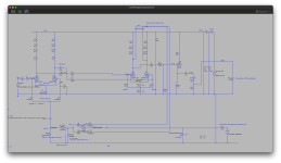
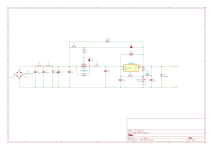
Next the schematic of the compressor itself:
Screenshot 2025-08-19 at 20.56.06.png

Next up is the maida regulator, I made a number of changes to that and listed that in the post here: https://forum.pedalpcb.com/threads/high-voltage-hijinks.26775/post-345139 saves on repeating that.

What this regulator does is basically take the 1V ripple from the RCRC filter and reduces the ripple massively so that it doesn't cause a problem for the highly sensitive signal path. It's in the order of mV ripple on 350Vdc!
 
Last edited:
COMPETITION ENTRY
Post 1/3 - Overview.

Entry: A prototype 176-inspired class A tube compressor.

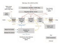
This is complex, so before we get to the build images, I will walk you through the architecture. After that, the schematics and build images will make sense.

Screenshot 2025-08-20 at 16.12.43.jpg

The system is split to three main areas, here's a little overview for each area which should help with the schematic and the final build pictures.

Area: Power
Wall mains input 253Vrms 50Hz, ~350Vdc output with <3mVpp ripple. This provides the power for the tubes "B+".
It does this in three steps - a torrid transformer provides a 234V primary to 234V secondary, or 1:1, so our input ends up being the same as our wall voltage. It's rectified and the resulting 350Vdc then goes through a RCRC filter providing 1Vpp of noise ripple.
The next step is it goes through a special voltage regulator that reduces the noise from 1Vpp to <3mVpp so our tubes are quiet when handling the guitar signal. The B+ drops a little due to this regulator and we finally get around 330Vdc "B+" to the anodes of each of the triodes.

Area: The signal path
The guitar signal goes through three stages: 1. a variable-mu triode pair that compresses the signal, 2. a constant gain stage pair, and, 3. a cathode follower driver output stage.

Why use two pairs of triodes for each stage?
It's to lower noise, and allows cancellation of noise.

How does the variable mu compress?
A triode is the same as a n-channel mosfet. The voltage difference of the control grid in relation to the cathode voltage changes the current allowed to flow from cathode to anode (plate). I won't go into the all the details but suffice to say, the "variable" part of the variable mu simply attenuates by reducing the DC voltage of the control grid. The tube then lowers the current flow and so you get a reduction of signal. To make it louder, the opposite occurs.
The second stage just amplifies the signal so we have a loud signal to work with, and the cathode follower provides a low impedance output to drive the next stage outside of the tube compressor circuit.

Area: The control board
This controls the variable-mu compression by watching the signal output from the signal stage 2. If it's a stronger signal, then the control board will make the variable-mu reduce the gain, thus compressing the signal. Likewise if the signal is weaker, the control board will increase the variable-mu gain again. There's two controls 'attack' and 'release', attack defines how fast the compressor reacts to strong signals and release defines how fast it goes back to normal.

The way it does this is to rectify the stage 2 signal itself - the louder the signal the more the diode rectifies so more current flows and charges a small capacitor up - it's this capacitor that the attack and release control, in a standard capacitor charge/discharge curve. When there's less signal, the capacitor simply discharges reducing the compression.


Next will be the schematic in a few hours time after it's moved over to KiCad..
 
Last edited:
Post 2/3 - the schematics.

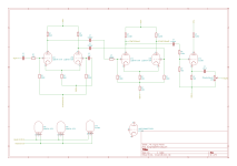
Signal Path Stages:
1. Variable Mu
2. Constant Gain
3. Output Driver
1755730716948.png

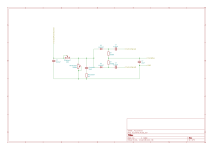
The Control for the Variable Mu:
1755718578956.png
Power filter and regulator:
1755729525160.png
The little TVtrim pot allows the fine tuning, if your primary voltages differ from mine, you will need to adjust this too. The output is 330Vdc. However the input RCRC network need to cope with 350Vdc.

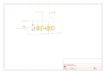
Relay for bypass switching
1755730417089.png
The guitar and amp grounds are straight to GND and aren't shown.

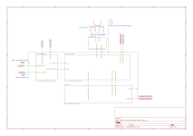
And top level sheet:
1755733039221.png
Note I've not shown the primary side - this will very between countries, for me it's connecting the primaries into 117-0-117 in series so I get 234V primary (my maths failed on the diagram - it's midnight here).. On the primary side there is a fused IEC going into a switch and also a MOV on the primary side to prevent voltage spikes when the power is switched off. If that's not in there it will blow fuses.
As my wall voltage hits 230Vrms +10% = 253Vrms, the secondary side of transformer hits 253Vrms (assumes 0% tolerance) which then rectifies to 253*1.4=354V peak for DC. Note the transformer I am using can suppy 540mA (120VA) so it’s less likely to drop that peak. So after diodes and RCRC I’m seeing around 347-350V.

The global tags show the points for the heater, relay and bias reference voltage power supplies. They're bench supplies.

Edit:
Errata - the R7 in the first diagram is incorrect, a cut and paste error. I will update tomorrow morning.
 
Last edited:
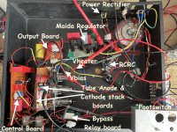
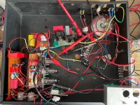
So here's an annotated image, this should make more sense now given the above information.

Note I have resistors in series to make up values that are shown in the schematics. The two parallel caps are the 0.30uF decoupling caps in the schematics.

Annotated Build.jpg

The input is the small wire I need to use a croc clip on the 1/2" input because I don't have another socket.
The output are the three wires that the bottom that go to a 1/2" socket that doesn't have a nut. This provides the grounding connection.
The clip/prove at the very top is my B+ monitoring DMM.. it's on when the device is plugged in and the last thing switched off - it tells me the voltage that feeds into the regulator. It usually reads around 345-350Vdc.
The boards support a set of trim pots, these have been set to the resistance values in the schematics. The pots for attack, release and output level are the three pots bottom left.

Tubes are bottom to top: 1st stage variable mu 12BH7A, 2nd state constant gain 12BH7A and 3rd stage ecc99.

Ignore the PNPs on the heat sink on the right.. they're just disconnected leftovers from the previous use.

"Clean" version.
TC_non-annoted.jpg

Demonstration.

Signal generator+Scope

You can see the purple showing input, and the yellow output that's attenuated.

Next you can see better with the guitar signal, the attenuation, Guitar+ scope

Then finally we have the guitar and amp..

Guitar + Amp
 
Last edited:
Back
Top