Switch simulator - bypassing pedal auto power-on state

CA138

Well-known member
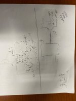
Hi, I have a few Boss and other pedals (some analog, some digital) in my rack that annoyingly power up with the effect disabled.

I believe this solution is the least-intrusive way of solving that issue - it simulates a footswitch press after a short delay when powering up. I would have been happy to buy and install a few of these boards but the website/contact have been unresponsive.

Is anyone aware of a similar solution or DIY board that can do this? I have no experience with Arduino but could put it together and hook it up easily if pre-programmed.
 
That’s a cool idea. The circuit looks a bit odd to me, in that when the micro-sw pin is high and the physical switch is pressed (ground) the micro will be pushing out 50mA (5v / 100ohms). Whereas the datasheet says the max is 40mA per output pin. I wonder if that resistor could be increased without affecting the function.

Another way would be to replace the physical switch with a transistor, and re-route the physical switch to another micro input.


I don’t know if any off-the-Shelf solution but if you don’t find something I could help design it (either a fabbed pcb with smd chip like the example, or perfboard with a thru-hole chip if you have space.
Thanks so much for having a look. I don't want to impose on your time (or anyone else's), was just hoping someone may know of an existing product. It's such a niche use-case that I am guessing not.

Space wouldn't really be an issue - it would mainly be making a PCB and then programming the chip. I might put in on my project list to learn enough about Arduino to come up with something.
 
No problem at all. If you can shove a stripboard into the battery compartment, you could probably do this quite easily.

I use ATTINY85 chips a lot (with through hole pins for perf or strip board). It's like an arduino for when you only need 6 or less input/output pins. The coding is virtually the same as arduino, and you can use an arduino to get the code from your computer USB to the arduino to the ATTINY.

Basically the same concept as the article, which uses ATTINY13, similar chip I'm just more used to the 85. Pedalpcb also uses the 85 in the Intelligent Relay Bypass kit.

I drew it up so that there would be a BJT transistor instead of the 100ohm resistor, which will draw less current off the ATTINY pin. I think this should work, but it'd be good to test it out first.

I could arrange to send you some ATTINY chips with the code flashed on it (just pay me for the chip and the shipping). Again, if you're interested. The code would be very quick to write, basically similar to the article.
 
Last edited:
No problem at all. If you can shove a stripboard into the battery compartment, you could probably do this quite easily.

I use ATTINY85 chips a lot (with through hole pins for perf or strip board). It's like an arduino for when you only need 6 or less input/output pins. The coding is virtually the same as arduino, and you can use an arduino to get the code from your computer USB to the arduino to the ATTINY.

Basically the same concept as the article, which uses ATTINY13, similar chip I'm just more used to the 85. Pedalpcb also uses the 85 in the Intelligent Relay Bypass kit.

I drew it up so that there would be a BJT transistor instead of the 100ohm resistor, which will draw less current off the ATTINY pin. I think this should work, but it'd be good to test it out first.

I could arrange to send you some ATTINY chips with the code flashed on it (just pay me for the chip and the shipping). Again, if you're interested. The code would be very quick to write, basically similar to the article.

Amazing, thankyou so much. I'll send you a message but would be very happy to pay for this if you don't mind and we can test it out.

If we can get it to work it will ultimately save me hacking apart some nice old analog Boss pedals to bypass the flip-flop circuit as well as messing with the newer ones (i.e. SDE-3 which is all SMD). Also, some EQD pedals with their flexi-switch don't have a way to change the default on/off state which is annoying.
 
I'ma little late to the party, but just to throw out another option, this is exactly the sort of thing a 555 timer is good for. No code required, but maybe a little more circuit work.
Thankyou for the suggestion. Do you think this method would require less modification than simply tapping into the 9V rail and existing switch?
 
Thankyou for the suggestion. Do you think this method would require less modification than simply tapping into the 9V rail and existing switch?
I'm proposing the 555 as an alternative to the ATtiny for generating the startup pulse as in the linked article. The amount of modification would be the same. The main advantage would be avoiding the need for firmware, for anyone who lacks the tools to flash a microcontroller.
 
That’s a nice idea. I wouldn’t know how to make the circuit for the 555. For this specific project I don’t mind helping with the attiny. But yeah would be nice to make it easier to use
 
Back
Top