Hey all!
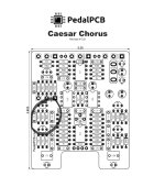
First time poster here, second PedalPCB board build. Havin some trouble getting my Caesar to work. Got an audio probe on the way from Rattlesnake to go on a part by part hunt, but i figured i'd drop this line first to see if anyone wanted to lend a helping hand.
Similar to other posts i've seen on the subject, i'm getting output issues and there are some weird IC values i'm registering at the same time. Here is a rough outline of the things going on:
1) All LEDs are functional, including the two indicators when toggle engaged. All pulsing seems appropriately timed.
2) True bypass works great, and without any supplemental noise that i would assume is a grounding issue.
3) Only get a slight whisper of a signal when pedal is engaged, input maxed out on a high gain pedal, and blend is CCW. This only present in a smaaaaall subset of the trim pot setting. Following recommendations i've seen, i found the pop on the trim pot and adjusted ever so slightly to get this sound. Otherwise pretty much silent.
4) Had my friend look over some multimeter values and he said the 4558D is acting weird. the vrefs aren't correct and 1/2 pins are giving values. here are those numbers
1: 8.36 // 2: 8.33 // 3: 0 // 4: 0 // 5: 0 // 6: 2.47 // 7: 8.46 // 8: 9.15
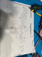
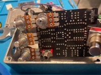
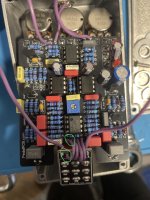
5) Friend's recommendation was to reflow resistors and caps that feed into 4558D. I figured i'd ask this forum for more guidance. I'll be sure to post some images of my board shortly as well.
Thanks for all your help!
First time poster here, second PedalPCB board build. Havin some trouble getting my Caesar to work. Got an audio probe on the way from Rattlesnake to go on a part by part hunt, but i figured i'd drop this line first to see if anyone wanted to lend a helping hand.
Similar to other posts i've seen on the subject, i'm getting output issues and there are some weird IC values i'm registering at the same time. Here is a rough outline of the things going on:
1) All LEDs are functional, including the two indicators when toggle engaged. All pulsing seems appropriately timed.
2) True bypass works great, and without any supplemental noise that i would assume is a grounding issue.
3) Only get a slight whisper of a signal when pedal is engaged, input maxed out on a high gain pedal, and blend is CCW. This only present in a smaaaaall subset of the trim pot setting. Following recommendations i've seen, i found the pop on the trim pot and adjusted ever so slightly to get this sound. Otherwise pretty much silent.
4) Had my friend look over some multimeter values and he said the 4558D is acting weird. the vrefs aren't correct and 1/2 pins are giving values. here are those numbers
1: 8.36 // 2: 8.33 // 3: 0 // 4: 0 // 5: 0 // 6: 2.47 // 7: 8.46 // 8: 9.15
5) Friend's recommendation was to reflow resistors and caps that feed into 4558D. I figured i'd ask this forum for more guidance. I'll be sure to post some images of my board shortly as well.
Thanks for all your help!


") ))
))