- Build Rating
- 4.00 star(s)
Here's my take on @Chuck D. Bones's Hybrid Fuzz Driver Deluxe. A long time ago, I built the Skreddy "Holy Trinity" using PedalPCB's Aldrin Fuzz PCB: The Lunar Module (Aldrin Fuzz stock), Hybrid Fuzz Driver, and Screwdriver. I've done a lot of builds using this core topology. One of my longstanding, all-time favorites is Chuck's modified Animals Diamond Peak and more recently a tweaked Animals Pedals/Skreddy Major Overdrive, the Old Fashioned.
Looking back to when I built the Hybrid Fuzz Driver, I really liked the drive/clipping character, but I was never quite satisfied with the EQ. I've long since parted with that build, but when Chuck worked his magic on the circuit, I knew it was time for another look.
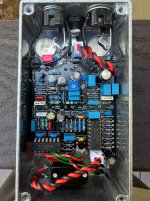
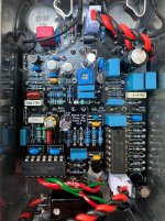
The actual effect circuit is faithful to Chuck's schematic. I just added my standard overkill features of P-MOS reverse polarity protection, extra power supply filtering, and buffered electrical bypass. For the buffer, I used a bootstrapped NPN BJT (aka the "Cornish buffer").
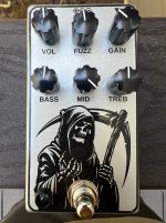
Everything worked on first power-up. I biased Q3's collector at 5v (or at least I thought I did), per Chuck's suggestion. As I started playing, I was somewhat disappointed. The drive character wasn't anything like I remembered; the overall tonality was very brittle - overemphasized highs, spiky, unmusical clipping. And I initially thought I wired the bass and treble pots backwards. But then I realized the pots were wired correctly, it was the enclosure labels that were swapped. This isn't the first time I've done this. Anyway, I kind of put it aside for a day or two. Today I thought I'd mess with Q3's bias again, to see if that improved the sound. The first thing I noticed: bias was actually 8v! I'm not sure how that happened. So I set it to 5v, and wow! that's the Hybrid Fuzz Driver mojo I remembered.
Edit: I should mention, Q2 and Q3 are the "money" transistors: I used low-gain silicon here, metal can 2N2369. I can't remember what HFE they are, but I think they are around 60. These are my favorite in the Diamond Peak, so they seemed a safe bet for the HFD Deluxe.
The enclosure itself is a bare aluminum 125B. I used 180 (I think) grit sandpaper and an orbital sander to do a bit of "polish" on the front face. Art and labels are a Sunnyscopa film-free laserjet decal. This is one of my best transfers ever. I went back to the original "W1+" glue, rather than using the GW1-PRO glue that's given me so many problems. Despite being one of my nicest finishes, I might still sand it down and re-apply, since the bass and treble labels are swapped.
Anyway - this a great circuit, and worth your time if you're a fan of YASF (yet another Skreddy fuzz). I have spare PCBs I'm happy to give away, just PM me if you'd like one.
Edit2: I posted the Gerbers and other supporting docs below in post #9.
Looking back to when I built the Hybrid Fuzz Driver, I really liked the drive/clipping character, but I was never quite satisfied with the EQ. I've long since parted with that build, but when Chuck worked his magic on the circuit, I knew it was time for another look.
The actual effect circuit is faithful to Chuck's schematic. I just added my standard overkill features of P-MOS reverse polarity protection, extra power supply filtering, and buffered electrical bypass. For the buffer, I used a bootstrapped NPN BJT (aka the "Cornish buffer").
Everything worked on first power-up. I biased Q3's collector at 5v (or at least I thought I did), per Chuck's suggestion. As I started playing, I was somewhat disappointed. The drive character wasn't anything like I remembered; the overall tonality was very brittle - overemphasized highs, spiky, unmusical clipping. And I initially thought I wired the bass and treble pots backwards. But then I realized the pots were wired correctly, it was the enclosure labels that were swapped. This isn't the first time I've done this. Anyway, I kind of put it aside for a day or two. Today I thought I'd mess with Q3's bias again, to see if that improved the sound. The first thing I noticed: bias was actually 8v! I'm not sure how that happened. So I set it to 5v, and wow! that's the Hybrid Fuzz Driver mojo I remembered.
Edit: I should mention, Q2 and Q3 are the "money" transistors: I used low-gain silicon here, metal can 2N2369. I can't remember what HFE they are, but I think they are around 60. These are my favorite in the Diamond Peak, so they seemed a safe bet for the HFD Deluxe.
The enclosure itself is a bare aluminum 125B. I used 180 (I think) grit sandpaper and an orbital sander to do a bit of "polish" on the front face. Art and labels are a Sunnyscopa film-free laserjet decal. This is one of my best transfers ever. I went back to the original "W1+" glue, rather than using the GW1-PRO glue that's given me so many problems. Despite being one of my nicest finishes, I might still sand it down and re-apply, since the bass and treble labels are swapped.
Anyway - this a great circuit, and worth your time if you're a fan of YASF (yet another Skreddy fuzz). I have spare PCBs I'm happy to give away, just PM me if you'd like one.
Edit2: I posted the Gerbers and other supporting docs below in post #9.
Attachments
Last edited: