


beansell
Member
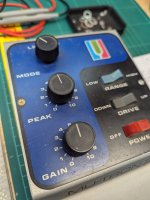
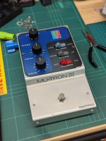
I sold a couple pedals recently, and the customer asked me to get his old Mu-Tron III going again. I'd built a couple Fuzzdog clones before, but never had my hands on a real one. This thing was in rough shape. Since being manufactured in the mid 1970s and making its way to Australia, apparently the previous owner had let it sit collecting dust until his old age, then sold it on.
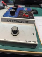
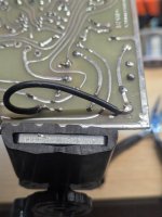
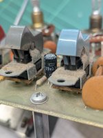
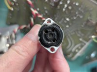
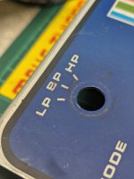
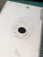
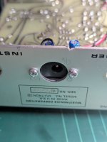
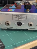
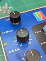
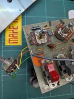
The footswitch had been swapped for a volume potentiometer (???), and a bodge wire added to keep the circuit in the 'always on' state. The toggle switches were full of crud, taking more than a few hesitant shots of Deoxit to bring them back to life. Luckily the rotary switch still worked just fine, I'm not sure I would have been able to successfully replace it. The potentiometers, unfortunately, were totally shot. Scratchy all the way around, plenty of dead spots. The knobs and enclosure had accrued the kind of filth that excites me to no end. I'd clean pedals all day if it paid the bills. To add a layer of complexity to the job, the DC input is a proprietary 3-pin connector that did not come with it's accompanying power supply. Yeesh.


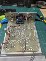
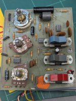
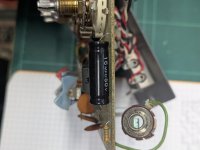
Trying to replace the potentiometers was tough (24mm knurled shaft C1M and A150k), and finding a supplier that also had the weird electrolytic capacitors (15uf 50V bipolar axial) was pretty tricky. It took a hot minute, but Retroamplis came through. I ended up ordering regular 16mm pots and manually offset them from the PCB with buss wire and some patient, careful soldering. I also referenced the wonderful documentation over here to fill some other gaps in my knowledge, and for the tip on adding a parallel resistor on lugs 1&3 to get a 150k sweep from a 250k pot.
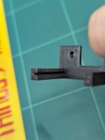
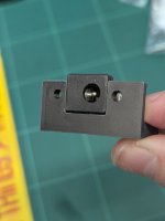
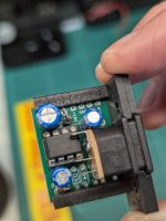
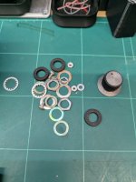
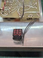
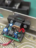
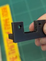
After giving it a thorough scrub inside and out, replacing the capacitors and potentiometers, I designed a 3D printed bracket around this circuit board from Fuzzdog, configured to deliver +9v, 0v, and -9v from a regular 9v input. The Boss style DC jack and PCB were press fit into the bracket, and I managed to scrounge up a couple M3 nuts and bolts to replace the old DC jack. I also had to run new wires for the DC jack and new footswitch.
I must have spent 20 hours on this project across 6 weeks. I certainly didn't undercharge the customer, but I value the learning experience pretty highly here. It's pretty satisfying to confidently take on a complex project like this. 2 years ago I'd feel like I'm way in over my head, sweating bullets worried that I'm gonna fuck up the PCB on a $1500 pedal.
I attached a bunch of photos below. Culled from a healthy 78 pics down to just the most important bunch. Not pictured are the heavily discoloured antibacterial wipes and gunk accrued on razor blades and cleaning picks, getting into every little crevice in screw heads, knob slots, and extra capacitors and potentiometers I mistakenly ordered from Mouser, turning out to be the wrong parts.
The footswitch had been swapped for a volume potentiometer (???), and a bodge wire added to keep the circuit in the 'always on' state. The toggle switches were full of crud, taking more than a few hesitant shots of Deoxit to bring them back to life. Luckily the rotary switch still worked just fine, I'm not sure I would have been able to successfully replace it. The potentiometers, unfortunately, were totally shot. Scratchy all the way around, plenty of dead spots. The knobs and enclosure had accrued the kind of filth that excites me to no end. I'd clean pedals all day if it paid the bills. To add a layer of complexity to the job, the DC input is a proprietary 3-pin connector that did not come with it's accompanying power supply. Yeesh.
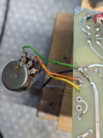
Trying to replace the potentiometers was tough (24mm knurled shaft C1M and A150k), and finding a supplier that also had the weird electrolytic capacitors (15uf 50V bipolar axial) was pretty tricky. It took a hot minute, but Retroamplis came through. I ended up ordering regular 16mm pots and manually offset them from the PCB with buss wire and some patient, careful soldering. I also referenced the wonderful documentation over here to fill some other gaps in my knowledge, and for the tip on adding a parallel resistor on lugs 1&3 to get a 150k sweep from a 250k pot.
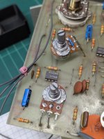
After giving it a thorough scrub inside and out, replacing the capacitors and potentiometers, I designed a 3D printed bracket around this circuit board from Fuzzdog, configured to deliver +9v, 0v, and -9v from a regular 9v input. The Boss style DC jack and PCB were press fit into the bracket, and I managed to scrounge up a couple M3 nuts and bolts to replace the old DC jack. I also had to run new wires for the DC jack and new footswitch.
I must have spent 20 hours on this project across 6 weeks. I certainly didn't undercharge the customer, but I value the learning experience pretty highly here. It's pretty satisfying to confidently take on a complex project like this. 2 years ago I'd feel like I'm way in over my head, sweating bullets worried that I'm gonna fuck up the PCB on a $1500 pedal.
I attached a bunch of photos below. Culled from a healthy 78 pics down to just the most important bunch. Not pictured are the heavily discoloured antibacterial wipes and gunk accrued on razor blades and cleaning picks, getting into every little crevice in screw heads, knob slots, and extra capacitors and potentiometers I mistakenly ordered from Mouser, turning out to be the wrong parts.
Attachments
-
 Oops.jpg359.7 KB · Views: 6
 -
 5 Repair 7.jpg306.9 KB · Views: 8
 -
 5 Repair 6.jpg314.8 KB · Views: 8
 -
 5 Repair 5.jpg362.4 KB · Views: 7
 -
 5 Repair 4.jpg348.8 KB · Views: 6
 -
 5 Repair 2.jpg366.1 KB · Views: 8
 -
 4 Clean 4.jpg301.3 KB · Views: 8
 -
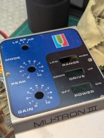 4 Clean 3.jpg348.1 KB · Views: 8
 -
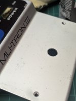 4 Clean 2.jpg229.8 KB · Views: 7
 -
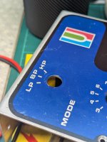 4 Clean 1.jpg319.1 KB · Views: 6
 -
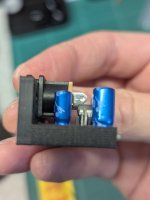 3 Bracket 5.jpg188.3 KB · Views: 5
 -
 3 Bracket 2.jpg160 KB · Views: 7
 -
 2 Mod 1.jpg324.6 KB · Views: 8
 -
 1 Original 6.jpg426.2 KB · Views: 9
 -
 1 Original 4.jpg259.7 KB · Views: 9