The MOD Squad

You should have a 10mm space since the pots use 10mm, I measured 10 1uF 630V caps from Tayda and 2 were under 10mm thick for my builds.
That's what I guessed (had a look at the datasheet of the pots). So, you also used the 1uF value for C2, right? I am wondering how the Bathtub sounds with the original value (22nF), since the filtering is also on the dry signal. Or am I wrong? I don't wanna try it, because I hate desoldering, especially on PCBs from overseas. ;-)
 
Hey Winterbloom,
To clarify what happens with C2:
- If you use a 0.47uF HV cap the dry HPF is set to around 20Hz.
- If you squeeze a 1uF cap in for C2, then you basically don’t have a HPF for the dry path at all. (Which may not be the better option as some sub-bass filtering can be helpful)
Whether you use a 0.47uF or a 1uF in C2, you are getting no audible bass cut, so if you have 1uF, use those (like I did).
I mentioned the 0.47uF HV caps because they are the limit to how small I’d recommend while being smaller and cheaper if people wanted that option.
With my mod, the switched caps only apply a HPF to the reverb effect.
The original needed the 22nF C2 cap as it provided a simple and effective HPF for the reverb to stop it sounding muddy without complicating the circuit and keeping costs down.
I’d love to know how you go with your build ☺️
 
Nobelium 2 stage HPF mod.
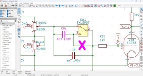
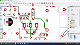
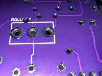
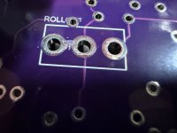
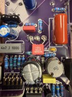
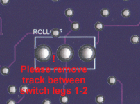
To make the HPF switch have 2 values you have to replace the ON-ON switch with an ON-OFF-ON 3 position switch, remove a small copper trace on the switch side of the PCB that connects terminal 2 to terminal 3 of the switch and then put another capacitor from terminal 1 to terminal 3 of the switch. BE VERY CAREFUL cutting into the PCB when removing the track between terminal 2 and 3 on the switch, use a very sharp knife and score it next to the pads and gently lift it out, remember the PCB is most like multilayer and we do not want to cut into any internal copper layers.
SamuelG might know the best value for the extra capacitor, I just add another 4n7 capacitor when I do it.
In one of the pictures it says please remove track between switch legs 1-2, it should say 2-3. I think the pictures explains it easy enough.

The original circuit has C8 always in the circuit and when you turn the HPF off you simply short C8 out with the switch and the signal goes straight past the capacitor.
When you turn the HPF on the switch opens and the signal goes through C8, all the mod does is add another capacitor (C8a) in parallel with C8 to increase the capacitance and thus lowering the HPF frequency.
In the switch left position C8 is shorted out, in the middle position the signal goes through C8 and in the right position the signal will go through C8 and the extra capacitor C8a.

 

Attachments

  • Nobelium HPF Circuit Mod.jpg
    Nobelium HPF Circuit Mod.jpg
    232 KB · Views: 5
  • Nobelium HPF Modded PCB.gif
    Nobelium HPF Modded PCB.gif
    377 KB · Views: 5
  • IMG_1662.JPG
    IMG_1662.JPG
    443.5 KB · Views: 5
  • IMG_1665.JPG
    IMG_1665.JPG
    278.7 KB · Views: 5
  • Nobelium Added Capacitor.jpg
    Nobelium Added Capacitor.jpg
    496.8 KB · Views: 6
  • Nobelium PCB Back Switch Track.gif
    Nobelium PCB Back Switch Track.gif
    136.2 KB · Views: 5
Back
Top