

Chuck D. Bones
Circuit Wizard
Beetronix produced a sweet sounding pedal, as demonstrated by Michael. The PPCB schematic looks like this...

A very clever design. Beetronix does a very good job managing gain and headroom. The 1st stage (IC1.1) has variable gain from -38dB to +8dB. The max gain is low enough that IC1.1 never saturates (unless you drive this with a booster). The 2nd stage is your typical JFET gain stage except for a feedback resistor (R4) that does nothing because the resistance is way too high. More on that later. Only about 4% of Q1's output is fed to Q2, owing to voltage divider R6 & R7 and load resistor R11. Q2 forms a similar JFET gain stage, with the same useless feedback resistor. C7 provides some low-pass filtering around 2KHz. Q3 buffers the output of Q2 and drives the Tone network. R13 & R14 provide 12dB attenuation, which ensures that IC1.2 doesn't saturate. IC1.2 is the typical TS-style Tone network, except the TONE pot is B100K. Not a good choice IMHO. Between 1 & 9, the gain at 3KHz varies by ±4dB. Below 1 or above 9, the gain jumps by 7dB (plot see below). C10 & R18 provide low-pass filtering below 7.2KHz. The output stage, IC2.2, provides 6dB of gain (when VOLUME is cranked) and undoes the inversion in IC1.1. We get a little more low-pass filtering from R20 & C12 at 4.8KHz.
This is all well and good, but there are a few things we can tweak.
First off, we can ditch R4 & R10 because they do nothing. There is a perfect place to add a BASS control, between IC1.1 and Q1. We replace C3 with 22nF and R5 with an A100K pot and a 6.8K resistor. With BASS dimed, it's every bit as fat as the original circuit. As we turn BASS down, the tone gets tighter. With BASS dialed all the way down, a good portion of the midrange is reduced, which reduces the apparent gain. One way to recover the lost gain is to change the attenuation between the 2nd & 3rd stages. That's what the RANGE switch does. In the left position, the attenuation is the same as the original circuit, about -28dB. In the center position, the attenuation is only -2dB. The right position provides a middle-ground attenuation of -12dB. Beetronix reduced the signal going into the Tone network after Q3 to maintain headroom. I think that attenuating the signal before Q3 is a better option. That's what R9 & R13 do. I could have left Q3 as a BJT, but I wanted to go all FET, so I changed Q3 to a BS170 MOSFET. I adjusted C7 to get the low-pass corner back where it belonged at 2KHz. The Tone network is the same, except I changed the TONE pot to B10K. The output stage is untouched, except I increased C13 to 1uF. With BASS dimed and RANGE in the right-hand position, it sounds just like the original circuit. There is one other thing we may want adjust, and that's the TONE freq range. In the original circuit, the TONE knob affects everything above 370Hz. That includes most of the midrange, which is why the TONE knob affects the volume so much. C9 could be reduced to 22nF or even 15nF to give the TONE knob more of a treble focus. I'm running 22nF on the breadboard right now and that sounds about right to me.

This is the TONE sweep with the original circuit.

This is the Tone sweep with the TONE pot changed to B10K. Same range, much smoother sweep.

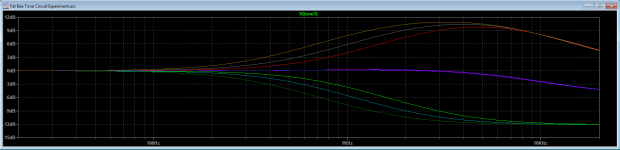
Here's the effect of changing C9. The TONE pot is set to 0, 5 & 10. C9 is stepped from 15nF (light green & red) to 22nF (turquoise & gray) to 33nF (dark green & brown).
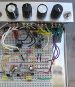
I almost forgot the obligatory breadboard pic. IC1 is top right, IC2 is top left. Q1 is bottom right, Q2 is bottom center, Q3 is bottom left.
Knobs (L-R): VOLUME - TREBLE - BASS - GAIN - RANGE sw

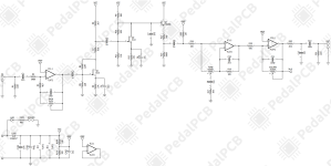
A very clever design. Beetronix does a very good job managing gain and headroom. The 1st stage (IC1.1) has variable gain from -38dB to +8dB. The max gain is low enough that IC1.1 never saturates (unless you drive this with a booster). The 2nd stage is your typical JFET gain stage except for a feedback resistor (R4) that does nothing because the resistance is way too high. More on that later. Only about 4% of Q1's output is fed to Q2, owing to voltage divider R6 & R7 and load resistor R11. Q2 forms a similar JFET gain stage, with the same useless feedback resistor. C7 provides some low-pass filtering around 2KHz. Q3 buffers the output of Q2 and drives the Tone network. R13 & R14 provide 12dB attenuation, which ensures that IC1.2 doesn't saturate. IC1.2 is the typical TS-style Tone network, except the TONE pot is B100K. Not a good choice IMHO. Between 1 & 9, the gain at 3KHz varies by ±4dB. Below 1 or above 9, the gain jumps by 7dB (plot see below). C10 & R18 provide low-pass filtering below 7.2KHz. The output stage, IC2.2, provides 6dB of gain (when VOLUME is cranked) and undoes the inversion in IC1.1. We get a little more low-pass filtering from R20 & C12 at 4.8KHz.
This is all well and good, but there are a few things we can tweak.
First off, we can ditch R4 & R10 because they do nothing. There is a perfect place to add a BASS control, between IC1.1 and Q1. We replace C3 with 22nF and R5 with an A100K pot and a 6.8K resistor. With BASS dimed, it's every bit as fat as the original circuit. As we turn BASS down, the tone gets tighter. With BASS dialed all the way down, a good portion of the midrange is reduced, which reduces the apparent gain. One way to recover the lost gain is to change the attenuation between the 2nd & 3rd stages. That's what the RANGE switch does. In the left position, the attenuation is the same as the original circuit, about -28dB. In the center position, the attenuation is only -2dB. The right position provides a middle-ground attenuation of -12dB. Beetronix reduced the signal going into the Tone network after Q3 to maintain headroom. I think that attenuating the signal before Q3 is a better option. That's what R9 & R13 do. I could have left Q3 as a BJT, but I wanted to go all FET, so I changed Q3 to a BS170 MOSFET. I adjusted C7 to get the low-pass corner back where it belonged at 2KHz. The Tone network is the same, except I changed the TONE pot to B10K. The output stage is untouched, except I increased C13 to 1uF. With BASS dimed and RANGE in the right-hand position, it sounds just like the original circuit. There is one other thing we may want adjust, and that's the TONE freq range. In the original circuit, the TONE knob affects everything above 370Hz. That includes most of the midrange, which is why the TONE knob affects the volume so much. C9 could be reduced to 22nF or even 15nF to give the TONE knob more of a treble focus. I'm running 22nF on the breadboard right now and that sounds about right to me.
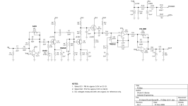
This is the TONE sweep with the original circuit.
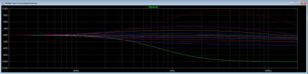
This is the Tone sweep with the TONE pot changed to B10K. Same range, much smoother sweep.
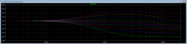
Here's the effect of changing C9. The TONE pot is set to 0, 5 & 10. C9 is stepped from 15nF (light green & red) to 22nF (turquoise & gray) to 33nF (dark green & brown).
I almost forgot the obligatory breadboard pic. IC1 is top right, IC2 is top left. Q1 is bottom right, Q2 is bottom center, Q3 is bottom left.
Knobs (L-R): VOLUME - TREBLE - BASS - GAIN - RANGE sw
Last edited:


 Amazing how many parts you find in circuits that are doing nothing.