1/8w resistor confusion

ac30irons

Active member
Hey all,

So I am thinking about doing some layouts with 1/8w resistors as I am only using 50x50 boards and space can be tight.

I’m bewildered though…

Everything I read says that the lowest ohm resistor you can use is around 650r if running 9v and connected to the power rail. 1/4w resistors half.

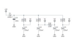
So riddle me this and educate me please. I’m a bit of a Cornish nut. Here is a snippet of a typical Cornish power section. It’s designed for 1/4w but every resistor here is half or under the resistance Ohms law says it should be.

What am I not understand ???

IMG_0100.jpeg

Thanks in advance people of the guitar pedal world !
 
The wattage rating limitation is also dependent on the current draw of the circuit. For circuits that draw just few mA, ⅛W is fine. Ohm's Law math will get you actual limits.
Thanks man - when you say a few - under any particular number ? I really find the maths side of things difficult !
 
That would be 650R from 9V directly to ground, none of the resistors in your schematic go directly to ground.... they're supplying current to the opamps and/or transistors in the circuit and those will all have a relatively high resistance to ground (compared to 150R).

You could connect one end of a 1 ohm 1/8W resistor to a 1000V supply and it won't get the slightest bit warm, as long as there is no path to ground on the other end of the resistor no current will flow, and no current means no heat.

Just looking at your snippet alone, (ignoring where VA, VC, VD, and VE connect in the rest of the circuit) there will be no current flow once C21, C22, C23, and C24 charge up fully. With no load aside from the capacitors, those resistors aren't going to burn regardless of their value, you could put a 0.01Ω resistor there and it won't even get warm. (Keep in mind, most circuits don't have those resistors and instead would have a solid 0Ω trace making that connection)

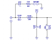
The resistors are added to improve the filtering between each of the power supplies.... Ever seen a schematic where they had a resistor before the filter cap? Like this? (R100 / C100)

What you're seeing in the Cornish schematic is exactly the same, he's just branched more than one supply off the main 9V line. (and VD is derived from VC, similar to what you see in tube amps)


1760182571552.png
 
Last edited:
That would be 650R from 9V directly to ground, none of the resistors in your schematic go directly to ground.... they're supplying current to the opamps and/or transistors in the circuit and those will all have a relatively high resistance to ground (compared to 150R).

You could connect one end of a 1 ohm 1/8W resistor to a 1000V supply and it won't get the slightest bit warm, as long as there is no path to ground on the other end of the resistor no current will flow, and no current means no heat.

Just looking at your snippet alone, (ignoring where VA, VC, VD, and VE connect in the rest of the circuit) there will be no current flow once C21, C22, C23, and C24 charge up fully. Those resistors aren't going to burn regardless of their value, you could put a 0.01Ω resistor there and it won't even get warm. (Keep in mind, most circuits don't have those resistors and instead would have a solid 0Ω trace making that connection)

The resistors are added to improve the filtering between each of the power supplies.... Ever seen a schematic where they had a resistor before the filter cap? Like this? (R100 / C100)

What you're seeing in the Cornish schematic is exactly the same, he's just branched more than one supply off the main 9V line. (and VD is derived from VC, similar to what you see in tube amps)


View attachment 104377
Thanks for such a comprehensive, and more importantly understandable reply.

This also answers another burning question I have had. So you can basically run different supply’s from the main 9v by branching off with a low ohm resistor. I was thinking of this when looking at doing several treble boosters in one box, but each had different filtering etc ! You’re going to say no now ain’t you …
 
Updated to clarify:

"With no load aside from the capacitors, those resistors aren't going to burn regardless of their value, you could put a 0.01Ω resistor there and it won't even get warm."

Things start to change when you add a significant load to those supplies... A couple opamps and simple transistor amplifiers aren't going to have an impact, but if you start throwing incandescent lamps (univibe), relay coils, microcontrollers, etc then you'd need to adjust the resistance and possibly wattage accordingly.
Thanks again Robert
 
Back
Top