anevilspar7an
New member
- Build Rating
- 4.00 star(s)
Not a complicated build but something I'm proud of.
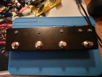
Left to Right: Ultra/Crunch Channel Select. Clean Channel Bypass. Effects Bypass. A/B Loop Selector.

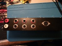
Left to Right, Top to Bottom: VOut. Out. Send A. Send B. VIn. In. Return A. Return B. DIN7 In.

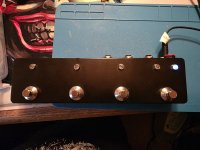
Channel A.

Channel B.

All point-to-point. Two separate grounds, one for the A/B switcher, the other for the DIN7.


Each connection has a color code for easy identification.

4PDT Footswitch to allow LED switching and grounding of opposing loop in use.

Switched VIn/VOut to allow use of regular 9V Center Negative power supply or VIn from DIN7.

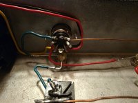
Counter-Clockwise starting at bottom right: VIn. VGND. GND. GND. Clean Channel Bypass. Ultra/Crunch Channel Select. Effects Bypass.

Left to Right: Ultra/Crunch Channel Select. Clean Channel Bypass. Effects Bypass. A/B Loop Selector.
Left to Right, Top to Bottom: VOut. Out. Send A. Send B. VIn. In. Return A. Return B. DIN7 In.
Channel A.
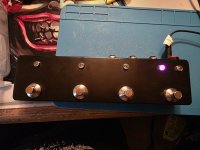
Channel B.
All point-to-point. Two separate grounds, one for the A/B switcher, the other for the DIN7.
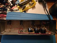
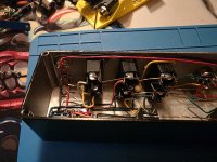
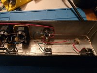
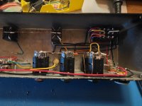
Each connection has a color code for easy identification.
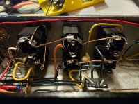
4PDT Footswitch to allow LED switching and grounding of opposing loop in use.
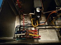
Switched VIn/VOut to allow use of regular 9V Center Negative power supply or VIn from DIN7.
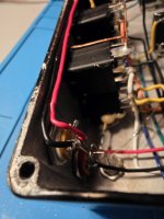
Counter-Clockwise starting at bottom right: VIn. VGND. GND. GND. Clean Channel Bypass. Ultra/Crunch Channel Select. Effects Bypass.
Last edited:
