A DIY 100 watt tube bass amp

Passinwind

Well-known member
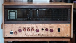
I'll do a full build thread here in the next few days, but I only got this thing running properly yesterday and need to do a bunch of detailing before I do gut shots.

PW100B_WIP10.png

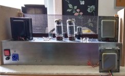
100 watts, 4 X EL-34, 1 x 12SL7, 2 x 12AU7

1/8th inch aluminum enclosure from here: https://landfallsystems.com/

Laser etched fascia plate from Marco Bass Guitars

Heyboer Hiwatt DR103 output transformer clone

Tube line driver based on the Aikido ones from Tubecad.com

Switchable input impedance (not yet implemented)

Power amp PCB and power transformer are NOS repair stock via friends from a now defunct amp company. Opamp input drives a stepup transformer which directly drives the EL-34s. Super low noise floor and an active bass or many pedals can drive the power amp board pretty well for practice purposes. I have a few rack and desktop preamps that work great into the Power Amp/Aux In jack too. Since there's a nice opamp power supply already on the power amp board I'm contemplating many SS add ons. The preamp build is highly modular and I left enough extra internal space to try many mods. Easy enough to drill more control holes and burn a new faceplate at any time as well.
 
Last edited:

PW100_wip.jpg

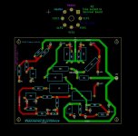
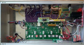
Power amp board, DC filament regulator, filament voltage elevator board, preamp B+ supply voltage drop/filter board, DIY tube socket breakout boards w/SMD grid stopper resistors right at tube pins.

PW6B_preamp_socketwiring.JPG

Preamp board originally from a rack preamp build in 2015, I would do many things differently by now. I think I see at least one labeling error there too.
 
Last edited:
Looks great! What are you using the DC for? The Novak and the OP amps?
The red board is a Glassware Audio 12V regulator for the preamp filaments, but that 12V rides on +68V derived by a splitter from the +280V preamp supply. This is done to keep cathode to heater voltages in bounds between the White Follower-ish (totem poled) line driver format and the typical common cathode gain stages.

The opamp runs off regulated +/-15V right on the power amp board (the gold heatsinks), off its own separate power supply tap. As you might imagine, ground management is hypercritical and there are a lot of ways to get it wrong. This is not exactly the most simple build, and it really helped to have the original power amp designer helping me out a little. He's doing bass amps at Mesa now, really great guy.
 
Yeah, grounding schemes between different regulated DC, elevated, B+ and audio can be hell. I usually go for buses that slowly branch out and are specific for each section and only meet at one point close to general ground. But never dealt with elevated…
 
Yeah, grounding schemes between different regulated DC, elevated, B+ and audio can be hell. I usually go for buses that slowly branch out and are specific for each section and only meet at one point close to general ground. But never dealt with elevated…
I used a little chassis ground isolator board a friend had shared on OSHpark and was careful about avoiding loopbacks, but the first time I used one of these power amps it totally gave me fits working out what went to dirty ground and what went to the clean side. I think I could still improve on that if and when I do a new preamp board, but with turret board wiring it could have been a lot easier! But I really dig doing PCB layout work, and hopefully getting smarter as I go.
 
New 100 watt output transformer finally installed now, old 50 watt one in foreground:


IMG_0936.jpeg

The mounting centers are only different by 1/16” and since my CNC map was done for the big one I didn’t have to modify anything but one wire pass-through grommet. The picture doesn’t quite convey the huge difference in mass between the two. Really looking forward to putting the amp through its paces tomorrow. Already brainstorming what I’m going to do with the fifty watt one, but not sure if I’ll go with something meant primarily for guitar or bass.
 
Last edited:
It's been a pleasure seeing this come together for you — thanks for letting us flies sit on the wall and watch.
Just finished bias calibration and power testing, it behaves exactly as expected. Glad I bought the TAD STR power tubes in 2020, the current pricing on a matched quartet has gone up over 50% by now.

I finished the board layout this morning for a variable HPF to go in this thing, but I already have so many pedals with one built in that I’m not sure it’s going to be worth the effort.
 
Last edited:
And now that I've had the chance to really wring the amp out for a couple of hours I don't think there's a single thing I want to change. Goes from super modern to Motown with my active fretless Marco Bass, noise floor is outstanding, and 100 tube watts in this format can easily get louder with no breakup than I'll ever need at home. The new output transformer really tightened up low bass response and between the bass control on the amp and the one in my bass I can get the vast majority of what an HPF would bring, and as I said I already have a zillion pedals with variable HPFs that I could bring into play if needed. On to the cooling vents and I'm calling it done for the moment. It's been quite a ride but I'm smiling now.
 
Last edited:
Congrats!

Needs some LEDs tho 😁
Originally an etched plexi front plate with LED backlighting was in discussion. But yeah, power and/or standby indicator lights wouldn't be a bad idea, and I think I probably saved a few nice jewel indicators when I sold off a big bag of them on eBay several years ago. The guy who sold me the power amp boards threw in a van load of all sorts of surplus MI electronics. Hundreds of fuses, a bunch of DSP boards, cab handles, a few power supplies, some preamp boards that went with the power amps, cabling and connectors, etc. I sold off a couple of hundred bucks worth on eBay and Talkbass and knocked down my cost on the power amps and power transformers quite a bit. It was an all or nothing deal, my friend just wanted to get all this stuff out of his shop,
 
Doing a LED front panel from your 12V DC is straightforward. Depending on how the standby is wired you could even do a dual Color for standby/on.

I went dual Color on my amp for the plexi front depending on the channel I am on. Three LEDs running at 50% of their max power is plenty enough really.
 
Doing a LED front panel from your 12V DC is straightforward. Depending on how the standby is wired you could even do a dual Color for standby/on.

I went dual Color on my amp for the plexi front depending on the channel I am on. Three LEDs running at 50% of their max power is plenty enough really.
The amp models the power amp boards came from just used a double pole switch for the standby and switched the light from the second set of poles. There are probably already header pins allotted to powers/standby lighting, I'll have to take a lot at the factory documents the designer gave me. But I'm kind of infamous for omitting LEDs on my personal pedal builds, or putting them on the back where I can only see them if I really need to. I can see the power tube filaments just fine through the front grill, so...
 
Last edited:
Back
Top