Paul.Ruby
Well-known member
I screwed up the thread title. Meant to say "... at PCBWay.com"
In order to embed reverb into a combo pedal, I've made a PCB in small format. My intent is to install an always-on reverb into a combo pedal and use trim pots to "set it and forget it." Here's one with alpha pots used for testing. It's almost identical to the Pythagoras with some minor exceptions. The LED is hooked to the clipping indicator from the FV-1. The output capacitor is increased to 2.2uf as I was getting some low end loss. I used SMD chips since I had to solder the FV-1 anyway. Easy to do on a hot plate with some solder paste on the pads.

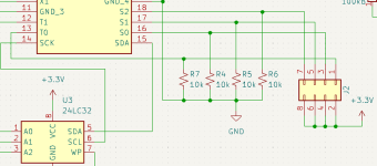
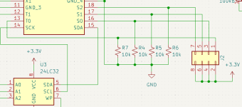
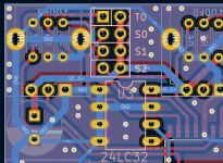
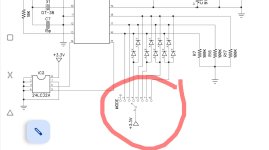
Eeprom and jumpers on the back for easy access. (I know the flux needs some clean up.)

Interactive BOM:
PCBWay link to the project (might not be live yet). I have a few left if anyone wants a PCB in the US. I will likely only use 5 of the 10 ordered. There is a BOM at this link as well with mouser links to all the parts. The links to POTs point to 12-turn trimmer pots that will fit but the footprint is for alpha 9mm vertical pots.

In order to embed reverb into a combo pedal, I've made a PCB in small format. My intent is to install an always-on reverb into a combo pedal and use trim pots to "set it and forget it." Here's one with alpha pots used for testing. It's almost identical to the Pythagoras with some minor exceptions. The LED is hooked to the clipping indicator from the FV-1. The output capacitor is increased to 2.2uf as I was getting some low end loss. I used SMD chips since I had to solder the FV-1 anyway. Easy to do on a hot plate with some solder paste on the pads.

Eeprom and jumpers on the back for easy access. (I know the flux needs some clean up.)

Interactive BOM:
PCBWay link to the project (might not be live yet). I have a few left if anyone wants a PCB in the US. I will likely only use 5 of the 10 ordered. There is a BOM at this link as well with mouser links to all the parts. The links to POTs point to 12-turn trimmer pots that will fit but the footprint is for alpha 9mm vertical pots.

Spin FV-1 Embedded Project Board - Share Project - PCBWay
This is a smaller version of the Pythagoras from PedalPCB.com for creating Reverb, Delay, Flange or Chorus effects. The intent is to make it as small as possible for embedding into a combo-pedal forma...
www.pcbway.com


