
jdduffield
Active member
Hi. I’ve been trying to figure out how I can use the Arachnid to make a single-patch FV-1 without loading in all of the diodes. Instead of the rotating 8-mode switcher, I hard wired what I believed to be patch zero in the EEPROM bank. I’m new to this so what am I missing?
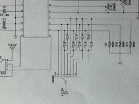
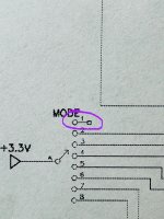
The schematic shows odd wiring for mode 1, which I assume corresponds to patch zero in the EEPROM bank (but not sure), … so, my thoughts are that the FV-1 translates that to mean “default to patch zero”. Is that incorrect? It didn’t seem like I’d need any diodes, but that may be where the breakdown is,… I’m not sure. If I need to load in some of the diodes, which ones? Thank you.
The dry signal works, but using the mix knob just mixes in some silence instead of the effect. I’ve tried loading the EEPROM up where every patch in it is the same effect. So, that rules out the possibility of it working as is for some other patch slot in the bank.
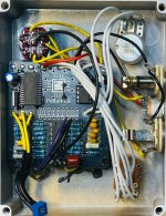
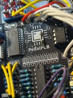
Attachments
Last edited: