

sam2020howard
New member
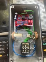
I have had this GCI boost for quite a while, and while I love what it does it is way, way, too loud. I’d like to get maybe like 60% of the volume but keep the distortion and eq sweep that come out of it, but I am wondering if you guys could advise on my options.
1) I’m aware I could probably get a volume pot in there, and that that would provide the most control, but it’s a brutal (in a cool way) looking pedal right now and I’d just as soon not add a knob. I thought about doing a trim switch on the side, but that may be too complicated for me to wire (I do have an on/on/on dpdt and lot of resistors though, if this is not as dumb in practice as it seems in my head)
2) My current solution is just to run it into a Keeley comp as limited. I don’t love this, as I still want it to push the pedal after it (Shallow Water), but with the compressor (or I guess limiter the way I’m using it) off the SW has so much headroom the output signal clips the next pedal
3) probably the easiest solution to my mind would be to hardwire a resistor somewhere in this circuit that doesn’t effect bypass, but limits the output. I just don’t know where to add that. My guess would be on the pcb side output cable?
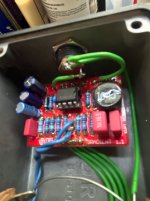
4) lastly, I could pull or add components to the board, but I’m having trouble finding any material on this circuit (correction: https://kurtballou.com/docs/GOD CITY INSTRUMENTS - Gradient boost V1.1 Build guide.pdf is a guide, I mean useful pertaining to making it less loud), and while it’s not functional to me at the moment, that doesn’t mean it won’t ever be, so I’d like to avoid destroying it in a way that I can’t troubleshoot (pulling components with unknown values and replacing them is a bit scary)
Any advice is appreciated. Thanks!
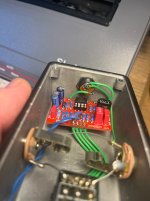
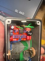
Photos attached
1) I’m aware I could probably get a volume pot in there, and that that would provide the most control, but it’s a brutal (in a cool way) looking pedal right now and I’d just as soon not add a knob. I thought about doing a trim switch on the side, but that may be too complicated for me to wire (I do have an on/on/on dpdt and lot of resistors though, if this is not as dumb in practice as it seems in my head)
2) My current solution is just to run it into a Keeley comp as limited. I don’t love this, as I still want it to push the pedal after it (Shallow Water), but with the compressor (or I guess limiter the way I’m using it) off the SW has so much headroom the output signal clips the next pedal
3) probably the easiest solution to my mind would be to hardwire a resistor somewhere in this circuit that doesn’t effect bypass, but limits the output. I just don’t know where to add that. My guess would be on the pcb side output cable?
4) lastly, I could pull or add components to the board, but I’m having trouble finding any material on this circuit (correction: https://kurtballou.com/docs/GOD CITY INSTRUMENTS - Gradient boost V1.1 Build guide.pdf is a guide, I mean useful pertaining to making it less loud), and while it’s not functional to me at the moment, that doesn’t mean it won’t ever be, so I’d like to avoid destroying it in a way that I can’t troubleshoot (pulling components with unknown values and replacing them is a bit scary)
Any advice is appreciated. Thanks!
Photos attached
Attachments
Last edited:
