Best way to go about A/B 2-In-1 Pedal

jmf0030

New member
Hello there! I'm new to the forum, and fairly new to building pedals. I had an idea that I'd like some input on.

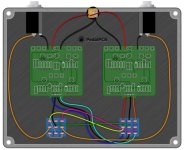
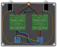
My two favorite Big Muff variants are the Ram's Head and the Op Amp, so I got the idea to make a 2-in-1 pedal for my board with A/B switching between them. I found this example wiring diagram on the main wiki. I believe it will work, but I'm unsure how to make the LEDs operate the way I want them to. Ideally, I'd like to have an LED tied to each effect to signify it is on and operational, while also having a third LED that is showing the pedal is receiving power (e.g. some sort of bypass, perhaps?).

Is this the route I need to go? Thank you all for reading, and any input would be appreciated 515px-2-in-1_AB.jpg :-)
 
So...

You want

STOMPER 1 = MASTER BYPASS

STOMPER 2 = A/B either/or


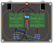
Do you want the POWER LED on all the time, or only when both circuits are bypassed, ie the POWER LED goes off when either circuit is engaged?


POWER LED only on when pedal is MASTER-BYPASSED / and POWER LED is off when either circuit is engaged:

JMF0030 515px-2-in-1_AB.jpg


[EDITED THE FOLLOWING FOR CLARIFICATION OF WHICH JUMPER TO ELIMINATE]
Nota Bene: the MASTER-BYPASS 3PDT's GROUND-jumper must be eliminated (not the bypass jumper, of course), or the POWER LED will be mixed up with the input signal when the pedal is engaged.
 
Last edited:
Thanks @Feral Feline!! I guess something I want to understand is if I built the pedal exactly as shown here and used the 2 LED's on the boards, what would the operation be?

Would the left footswitch control the power of the pedal and also turn on the LED for one of the circuits? Would the LED that is powered change between the circuits when pressing the other footswitch?

Edit: By "here" I mean the original image I linked for A/B operation.
 

Attachments

  • 515px-2-in-1_AB.jpg
    515px-2-in-1_AB.jpg
    42 KB · Views: 4
Thanks @Feral Feline!! I guess something I want to understand is if I built the pedal exactly as shown here and used the 2 LED's on the boards, what would the operation be?

Would the left footswitch control the power of the pedal and also turn on the LED for one of the circuits? Would the LED that is powered change between the circuits when pressing the other footswitch?

Edit: By "here" I mean the original image I linked for A/B operation.


Wired stock, as in your OP with the original image, the pedal functions as:

Bypass = no LED is lit​
Engaged = Whichever circuit is selected by the A/B-sw will have its LED lit up​

The left footswitch (when looking at the diagram, ie into the back of the pedal) is the Master Bypass.

The right footswitch (again looking at the diagram or into the open pedal's backside) is the A/B-Switch.


So, for example, in bypass you won't know which circuit is selected by the A/B-Switch until you hit the Master Bypass switch to activate the pedal.


If you need to know in advance which circuit will be active when you engage the pedal, I recommend this dimmer-concept:


Man, thank you so much for the thorough explanation. After some thought, I'm going to build its show in the OP.

Now just waiting on the PCBs I need to come back in stock... :alien:
 
Back
Top