Calamity Fuzz

Colum

New member
Hi all.
1st post and I hope you can help.

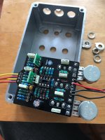
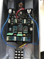
I built a Calamity Fuzz from a kit from Musikding. There is no sound when the peal is engaged. LED light up but zero sound. Not even faintly.
Iwas very careful and am sure it's all wired correctly. The only thing was Musikding omitted three 1m resistors from the kit so I used some cheap ones I had here. They have very thin leads. Would that make a difference? They are in R19 R20 and R23 of the diagram.
I don't have a multi meter at the moment but is there anything obvious here I've missed somehow?

Regrads

Colum
 

Attachments

  • Screenshot 2022-05-29 at 17.43.51.png
    Screenshot 2022-05-29 at 17.43.51.png
    48.3 KB · Views: 18
  • IMG_5884.jpeg
    IMG_5884.jpeg
    1.4 MB · Views: 16
  • IMG_5888.jpg
    IMG_5888.jpg
    1.6 MB · Views: 16
Can you take a picture of the solder side? Did you check all component values? I don’t know what the transistor orientation should be, you may want to double check that. Also did they give you the transistors with the kit? After visual inspection I would start by measuring transistor voltages.
 
Can you take a picture of the solder side? Did you check all component values? I don’t know what the transistor orientation should be, you may want to double check that. Also did they give you the transistors with the kit? After visual inspection I would start by measuring transistor voltages.
Hi Thanks for your reply.
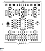
The transistors all came from the kit and are oriented according to the PCB. It can be seen in the first diagram with the flat side nearest the switch. I've checked the soldered side but it's all standard.

How would you measure transistor voltages and what should I be looking for?

Regards

Colum
With a digital multimeter (DMM), black (negative) pin to ground, red (positive) on the transistor pin (source, gate, drain). I haven’t looked at the schematic but common source stages (the most used in overdrives) typically have a drain voltage that’s half the power rail (4.5V).
 
With a digital multimeter (DMM), black (negative) pin to ground, red (positive) on the transistor pin (source, gate, drain). I haven’t looked at the schematic but common source stages (the most used in overdrives) typically have a drain voltage that’s half the power rail (4.5V).
Thanks I’ll have a look for a multimeter during the week
 
This circuit is persnickety and requires J201s with VERY LOW Idss and Vp. Take a look at this link, you are not the first person to have trouble with this circuit. Unless Musikding tested and selected J201s for this kit, it ain't gonna work. FYI, these forums have a search feature, you might try using it to see if others have solved the same problem you are having.
 
Back
Top Bottom