I'm working on a project ingetrating 2 FV-1 based pcbs in a single enclosure. This is for a someone in a studio application so I'm trying to make sure the noise floor is minimal. I'm considering these options:
--18V IN, 7809 regulators (the big ones) with appropriate capacitors.
--9V IN, use the 7805 & IEBs like the pedalpcb 4-Tap Converter/Isolator project
--Supply both with the same 9V in, hope for the best. But I've had noise from daisy chainging 2 FV-1 pedals in the past from a single 9V adapter, if I recall right.
I'm leaning toward the 7809s. Nice and simple. I don't think the 18V will be an issue since it shouldn't be moving around much.
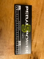
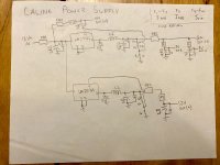
It did make me curious about the cheap Caline supply that I've had installed under the top row of my pedal board for about 10 years. Honestly, I haven't really had much trouble with it. Not knowing much about these, I thought maybe I'd see a 7809 for each channel. What I found was a bit different.
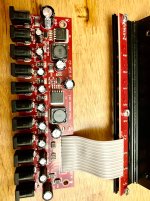
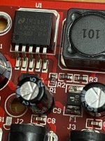
I was a bit surprised to see that all the 9Vs run off the same Buck converter (LM2576S), and that these outputs are only "isolated" from each other by the Fuses, and their own capacitors. I read that the Fuse can contribute some very small filtering (with the capacitor) due to it's inherent (very small) resistance and inductance). But suffice to say these are hardly isolated. However, I haven't had noticeble noise problems, even running multiple FV-1 pedals from it.
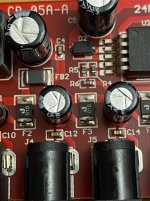
Also, the only thing that makes Jack 8 "500mA" is using a larger fuse. Maybe this is common. Since the LM is rated for 3A, 8x outputs all at 500mA would be too much, so it makes sense to limit most of them. I'm not sure why they couldn't have made the 12 and 18 500mA.
I checked the math and the resistors for feedback to Pin4 match the data-sheet equation to get 9V and 12V. The pcb attached by ribbon cable only contains the LEDs.
Also, side note, back when I installed it, I built a little 1590A 9V converter to convert the 12V and 18V both to 9V, so that I'd just have 10x 9V if I wanted. I used 7809 for this.
My understanding is that Buck regulators are more efficient and generate less heat compared to LDO regulators (like 7809). Buck are a type of switching regulator (data sheet says it's at 52kHz). Switching are more efficient, because they alternate from completely ON to OFF and in each state there is very little resistance. On the other hand, LDOs use a feedback FET in the linear range (where it acts like a resistor). So the Voltage drop is lost to "resistor" heat in that FET. This is the same concept that makes Class D (switching) power amps more efficient than transistor based.
--18V IN, 7809 regulators (the big ones) with appropriate capacitors.
--9V IN, use the 7805 & IEBs like the pedalpcb 4-Tap Converter/Isolator project
--Supply both with the same 9V in, hope for the best. But I've had noise from daisy chainging 2 FV-1 pedals in the past from a single 9V adapter, if I recall right.
I'm leaning toward the 7809s. Nice and simple. I don't think the 18V will be an issue since it shouldn't be moving around much.
It did make me curious about the cheap Caline supply that I've had installed under the top row of my pedal board for about 10 years. Honestly, I haven't really had much trouble with it. Not knowing much about these, I thought maybe I'd see a 7809 for each channel. What I found was a bit different.
I was a bit surprised to see that all the 9Vs run off the same Buck converter (LM2576S), and that these outputs are only "isolated" from each other by the Fuses, and their own capacitors. I read that the Fuse can contribute some very small filtering (with the capacitor) due to it's inherent (very small) resistance and inductance). But suffice to say these are hardly isolated. However, I haven't had noticeble noise problems, even running multiple FV-1 pedals from it.
Also, the only thing that makes Jack 8 "500mA" is using a larger fuse. Maybe this is common. Since the LM is rated for 3A, 8x outputs all at 500mA would be too much, so it makes sense to limit most of them. I'm not sure why they couldn't have made the 12 and 18 500mA.
I checked the math and the resistors for feedback to Pin4 match the data-sheet equation to get 9V and 12V. The pcb attached by ribbon cable only contains the LEDs.
Also, side note, back when I installed it, I built a little 1590A 9V converter to convert the 12V and 18V both to 9V, so that I'd just have 10x 9V if I wanted. I used 7809 for this.
My understanding is that Buck regulators are more efficient and generate less heat compared to LDO regulators (like 7809). Buck are a type of switching regulator (data sheet says it's at 52kHz). Switching are more efficient, because they alternate from completely ON to OFF and in each state there is very little resistance. On the other hand, LDOs use a feedback FET in the linear range (where it acts like a resistor). So the Voltage drop is lost to "resistor" heat in that FET. This is the same concept that makes Class D (switching) power amps more efficient than transistor based.