Carbon Black Fuzz Transistor Bias and Fuzz Control Question

Spark_Trooper84

New member
Hello all.
A couple of quick questions here.

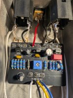
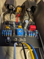
I just completed the Carbon Black Fuzz.

Firstly, I found and used 2n3903 transistors like the build documentation says to.
From reading up here, the bias trim pot is for Q3.
I'm getting readings of 7.65v to 8.04v on my multimeter at each end of the trim pot when measuring the collector leg.

I know that it's a 'trim by ear' sort of thing, but based around 4.5v, right?

Thing is, i can hear literally no difference when sweeping the trim pot.. so, is something going on that i have voltages in the high 7s, low 8s when it should be somewhere around 4.5v?

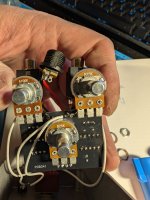
Secondly, the fuzz control.
I get literally no fuzz until i'm at like 90 percent dialed, and then it comes in all at once.
I used a B5k as the build docs state.

So, have I done something wrong or misunderstood something along the way?
 
something going on that i have voltages in the high 7s, low 8s when it should be somewhere around 4.5v?
yeah something's going on, you should be able to dial it around 4.5v (although it's a taste thing, i prefer around 5v)

what value is the bias trimpot?

have I done something wrong or misunderstood something along the way?
we will need clear, in-focus, detailed photos of both sides of the board/build to determine this.
 
yeah something's going on, you should be able to dial it around 4.5v (although it's a taste thing, i prefer around 5v)

what value is the bias trimpot?


we will need clear, in-focus, detailed photos of both sides of the board/build to determine this.
I'll preface to say that the board got assembled about a month ago, and only put in it's enclosure last week but i've been so busy that i hadn't been able to get around to messing with it until this evening.

I think I identified my Fuzz pot problem... The build docs call for a b5k, and it seems I put in a b25k... So, that should explain that end of things at least. I have a b5k on hand that I can place in that location once I desolder the b25k

The trim pot is a 10k per the build documentation, I confirmed it's markings against my mouser order on that.

The two resistors in R6 are 22k in series.
R6 calls for a 46k, but I did not have any on hand at the time, so I put those in series to come up to 44k. R6 on the schematic comes from vcc to the collector of Q2

I've confirmed all the other resistor values against the build documentation as well as the electrolytics.

Also, upon review of the board, I used 100n MLCCs in C2 and C4, whereas I could have used box film capacitors, those again I didn't have on hand at the time.
(i was waiting on a big order from Tayda to arrive at the time)
Could that be the issue? should I replace those with 100n box films?
 

Attachments

  • PXL_20260213_043510497.jpg
    PXL_20260213_043510497.jpg
    541.6 KB · Views: 5
  • PXL_20260213_043521884.jpg
    PXL_20260213_043521884.jpg
    522.1 KB · Views: 5
  • PXL_20260213_043751543.jpg
    PXL_20260213_043751543.jpg
    455.6 KB · Views: 5
build docs call for a b5k, and it seems I put in a b25k...
this will definitely fuck up Q3's idle bias.
once you've corrected this, check Q3c again.
The two resistors in R6 are 22k in series.
R6 calls for a 46k, but I did not have any on hand at the time, so I put those in series to come up to 44k.
shouldn't matter at all.
used 100n MLCCs in C2 and C4, whereas I could have used box film capacitors, those again I didn't have on hand at the time.
(i was waiting on a big order from Tayda to arrive at the time)
Could that be the issue? should I replace those with 100n box films?
doesn't matter. 100n is 100n, they should perform the same in this circuit.
 
this will definitely fuck up Q3's idle bias.
once you've corrected this, check Q3c again.

shouldn't matter at all.

doesn't matter. 100n is 100n, they should perform the same in this circuit.
ok, I'll be replacing the wrong pot with the correct one tomorrow and will report back,
Thanks for the input, and for prompting me to actually look at the pot..
Don't know how i mixed that one up.
 
this will definitely fuck up Q3's idle bias.
once you've corrected this, check Q3c again.

shouldn't matter at all.

doesn't matter. 100n is 100n, they should perform the same in this circuit.
ok, well... no change on the transitor bias front.

I changed out the fuzz pot to the correct b5k pot.
that seems to have mostly fixed that issue.

As for the transistors.
I'm still getting the same 7.65v to 8.04v range.
I'm also seeing a steady 7.48 on Q2's Collector leg.
To maybe better assist a troubleshoot, I took the following measurements on all three transistors.

I took these measurements while plugged into my guitar and amp and strumming the strings and the trim pot at it's lowest range.

With Volume at about 25% and Fuzz & Tone at full 'off'
Q1 7.49v Collector, 1.4v Base, .58v Emitter
Q2 1.50v Collector, .78v Base, .16v Emitter
Q3 7.65v Collector, 1.5v Base, .92 Emitter

With Volume at about 25% and Fuzz and Tone at about half
Q1 7.48c Collector, 1.21v Base, .61v Emitter
Q2 1.50v Collector, .78v Base, .16v Emitter
Q3 7.85v Collector, 1.56v Base, .92v Emitter

With Volume at about 25% and Fuzz and Tone at full
Q1 7.48c Collector, 1.21v Base, .61v Emitter
Q2 1.50v Collector, .78v Base, .16v Emitter
Q3 7.85v Collector, 1.56v Base, .92v Emitter

I do see a voltage drop on the Collector of Q3 with Fuzz control on full while strumming, but never below about 6.95-6.92v

All the parts were ordered from Mouser.
Here's the transistors I used:

I thoroughly inspected the board for any dead shorts and couldn't find any.
I've probed all around Q3 and it's connected components from the build doc schematic and i have continuity
If I weren't seeing voltage sweeps on the collector of Q3 when I sweep the trim pot, I'd almost say that the trim pot might be bad.

Like, it sounds ok, but i'm not sure if it's how it's supposed to sound or not given the apparent issue with the transistors seeing almost double the voltage they're 'supposed' to see.

I'm at a point now where I kinda want to get another board and redo it just to see.
I'm not incredibly happy with the enclosure I made for it, so a redo would be in the works anyhow.
 
I did just find this post from back in 2020 with the user saying his bias was at around 7.6v.
So, maybe it's just supposed to be like that?

 
Back
Top