Cattle Driver - circuit anomaly

aquataur

Member
I did not find a thread that this question would fit in so I opened a new one.
Admin please move if in the wrong section.

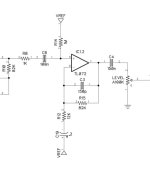
I just looked through the Cattle Driver schematic. I noticed that C19, which is in the ground leg of the output stage's feedback node, appears in the wrong polarity.
If the reference were GND, then it would certainly be the wrong way around. Since it is referenced to Vref, theoretically there is no DC across it, which raises the question, if the electrolytic functions properly.

Some designers use as reference Vref. Does somebody know if there is a genuine reason for this?
Theoretically, Vref is a hard rail, but it isn't really. I would use GND and flip the cap around.
The picture shows a fragment of the "official" pdf.

Any insights?

Edit: just saw that the (-) side of C11 has no DC reference either. Theoretically, an electrolytic cap in such a situation will not format its electrolytic properly.
 

Attachments

  • cattle_driver_fragment.jpg
    cattle_driver_fragment.jpg
    22.8 KB · Views: 32
Last edited:
Interesting!
I don't think there's much DC voltage across C11 or C19 in this circuit, just AC.
But you could always use a nonpolar electrolytic and thus be totally safe - seems the best choice.

I think most polar electrolytics should be ok w/ AC if they're rated for higher voltages, the dielectric is aluminum oxide and it can take it.
The polarity comes from the ionic conduction in the (typically) liquid electrolyte that forms the cathode.
If I used a regular electrolytic, I definitely would use a cap rated for a much larger voltage here than the supply voltage.

Added comment:
Actually, good electrolytic caps will have 2 different specifications, for maximum DC voltage and max AC voltage.


Edit: Ack, I'm wrong here, see below...
 
Last edited:
Right, if the don't have separate specs for max DC and max AC, look for text like this (from a Panasonic cap spec sheet):

The sum of DC and ripple peak voltage shall not exceed the rated working voltage
and then they provide a frequency correction for the ripple (ac) voltage:

1756770765589.png

Edit:
Ack, this is true, but it still doesn't address @aquataur's question regarding AC coupling when Vdc ~ 0.
 
Last edited:
That's really cool Darwin! How do you apply the correction factor? For example in this circuit, if C19 was 2.2uf (so I can follow from the table)
 
Actually, I may have goofed and gotten over my skis on this - let me do some refreshing on this tomorrow and report back.
And people who know this better can pipe in and answer (and correct my goofs).
But it is quite common to see electrolytics in use w/ close to ~0 Vdc across them, and yet passing AC signals.
So let me clean out some mental cobwebs and come back.

Edited.
 
Last edited:
For now, let me post this excerpt from this article on 'Electrolytics for AC Coupling' [https://northcoastsynthesis.com/news/electrolytics-for-ac-coupling/]

Here's a simplified equivalent circuit diagram (for a polar aluminum electrolytic capacitor).... It is based on a more detailed equivalent circuit (modelling more effects) in Bateman's article. [see https://linearaudio.net/sites/linearaudio.net/files/Bateman EW 12 2002 mar2003 1uF electrolytic or film.pdf]
Simplified equivalent circuit for an electrolytic capacitor
This equivalent circuit suggests that it may be okay to apply a little bit of reverse voltage to an electrolytic capacitor, like a couple of volts, because in that state D1 is forward-biased and D2 is not breaking down. But beyond that point, with larger reverse voltages, D2 is going into breakdown mode and some significant current may flow, limited by equivalent resistances not shown in this diagram. Whether the reverse current is damaging or just annoying, and how quickly it might be damaging,isn't obvious; but at least it isn't how the capacitor is meant to operate. We probably shouldn't put more than about 1.5V of reverse voltage across the capacitor. On the other hand, we probably can safely apply that much.

Note that the limit of 1.5V is determined by the thin oxide layer on the cathode foil, which is what Bateman calls "unformed" oxide. It is not directly related to the right-direction voltage rating determined by the other foil, and using a higher-voltage electrolytic capacitor would not necessarily increase the reverse-voltage limit. Nonetheless, as Bateman also describes, capacitor manufacturers for various reasons sometimes use"formed" oxide with a higher voltage limit on the cathode too, so it is possible, not guaranteed, that some polarized aluminum electrolytic caps could actually withstand significantly more than 1.5V in the reverse direction. Capacitors marketed as non-polarized are made with the same thick-oxide "anode foil" on both sides, so they can withstand the same relatively high voltage in either direction.


I am presently thinking that the ~1.5V "diode" voltage represent the chemical potential to begin disassociating the aluminum oxide, which can generate hydrogen gas and ultimately damage/destroy the capacitor when driven too far into reverse polarization.


Another document on this topic is by the capacitor manufacturer Cornell-Dubiier (CDE), see pp. 4-5 of https://www.cde.com/resources/technical-papers/KNO_CD_AEappGuide_R2.pdf


So the answer appears to be that for small ac signals, with |Vac| smaller than 1-1.5V, it's ok. But for larger amplitudes, those 2 caps in the Cattle Driver (and other similar circuits) should definitely be nonpolar.
 
Last edited:
Good readings.
C19 is 1µF, ok for a polyester cap. But C11 is 4.7µF - I need a bigger enclosure.
Analog Devices Design note SLYT796a-1: Selecting Capacitors to Minimize Distortion in Audio Amplifiers says: (page 4)
Electrolytic capacitors have polarized dielectrics, meaning their anode must be kept at a higher voltage than the cathode or else the capacitor may be damaged. (...)
Comparing (...) shows a significant difference in performance when polarized capacitors are not properly biased. High-performance applications must guarantee a
positive DC bias or avoid the use of polarized capacitors for AC coupling.
Note that they speak of "anode" and "cathode" (as mentioned above). When the bias voltage becomes very small the electrolytic begins to behave like a diode. The effect of this is explained here: soundQuality.org: Capacitors vs Sound Quality
Polarized Capacitors and Even-Order Distortion: Electrolytic and tantalum capacitors are polarized, meaning they are intended to see a DC bias of the correct polarity. If an AC signal causes voltage reversal or large swings across a polarized cap, the device may conduct asymmetrically (the dielectric may momentarily behave like a diode or be biased into a non-linear region). (...) Maintaining a DC bias on polarized caps in audio signal paths is a common technique to improve linearity – many amplifier designs provide a small bias across coupling electrolytics for this reason. TI’s tests mentioned earlier also illustrate that if an electrolytic or tantalum is used for AC coupling, it should be biased to avoid any reverse voltage. (...) In other words, a good electrolytic, used well within its linear region, can be effectively transparent in terms of THD – its imperfections are below audibility in most cases. However, this presumes it’s appropriately biased and sized so that the AC voltage across it is small.

Since we are speaking of a device whose purpose is to distort, the added distortion may be largely irrelevant, but the way C19 is mounted hurts the eye.
 
Last edited:
Upon second (or third) thought... C11 can be replaced by a bridge. There is blocking caps all over the tonestack.
It looks like this arrangement stems from an earlier design stage, where it was needed.

I tried it and it works. I also referenced C19 to ground with correct polarity without detriment.
 
More anomalies: Butler produces in the stage that drives the "distortion generator" (=tubes) a heavily low passed signal. Look up Madbean's Archibald schematic. A 500k drive pot together with a 120pF cap yields a 2.6kHz treble rolloff.
The Cattle Driver uses 50k and 50 pF (63 kHz). If you scale up the above values, the roll-off cap should be 1.2nF. Found it, tried it. Ice-pick is gone.
Correction. By happy accident, I had changed the feedback cap on the output stage. It is going to be 1500 pf (1.5nf) instead of 150p. This yields a roll-off starting around 1.3kHz. With this in place, the treble knob truly can sit at noon for a palatable tone. With gain dimed, some darkening of tone takes place, which is typical for this architecture. Changing the feedback cap of IC2 (distortion generator) has no effect until very large values.

I do not know what Buffalo FX used in the original, but it cannot possibly be what is in the Cattle Driver, because on videos both the solid state device and the tube device sound virtually identical with comparable treble knob settings.

The amp-style tone-stack is essentially the same. Looks like a Fender tone-stack with some mid-compensation.
 
Last edited:
Note that they speak of "anode" and "cathode" (as mentioned above). When the bias voltage becomes very small the electrolytic begins to behave like a diode.

There is a tiny asymmetry, but the distortion is quite small for an overdrive pedal. These two articles measure it.


Back
Top