peteraspholm
New member
First time posting, not experienced in circuitry.
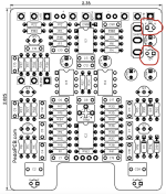
I'm building the Ceasar Chorus and the LED pins (D1, D2, circled in Red) are towards the top right section of the pcb template. But where I would put LEDs based on the layout of the drill map is circled in blue. I've looked up some other builds and from what I can see people are putting some kind of capacitor in place of the LED. Where do I put my LEDs, and if they belong in the blue circles, what do I replace them with for pins d1 and d2?

I'm building the Ceasar Chorus and the LED pins (D1, D2, circled in Red) are towards the top right section of the pcb template. But where I would put LEDs based on the layout of the drill map is circled in blue. I've looked up some other builds and from what I can see people are putting some kind of capacitor in place of the LED. Where do I put my LEDs, and if they belong in the blue circles, what do I replace them with for pins d1 and d2?