The schematic used for the Baron Samedi Vero below was shared years ago by Aditya of Animal Factory, but it's missing the fifth (Octave/Subs) pot. I figured "what the heck" and wrote him about it - after all, he shared the info and the Baron Samedi pedal isn't currently in production (but being retooled for V2!).
Turns out he's incredibly nice, and gave me a tip -"to add the fifth knob, find a way for that 470k resistor to go between 500k and say 47k."
I assume this means to omit the 470k resistor and add jumpers to those spaces on the Vero connected to a B500K pot? Do I also need to add a 47k resistor to the equation? I'd need to figure out which Vero space (top or bottom of that 470k area) to connect to Lug 2 and which one for Lug 3... if that IS what I need to do.
I'm learning, but still a beginner. Clearly. Situations like these help me understand what's going on, though! I really appreciate it.
If you want that 470K to vary between 47K and 500k you will need a 47K resistor in series with a 450K pot (or closest available value). Using lugs 1,2 or 2,3 will affect the direction in which the pot works (not sure what the intended behavior is). Also I don’t know which pot taper you are going to need.
With just a potentiometer, you’ll end up with a resistance range of 0 ohms up to the potentiometer’s value. If you want to change the start and end value of the sweep, you could add additional resistors in series and/or parallel to the pot. https://www.electronics-tutorials.ws/resistor/res_5.html
Based on the Vero above, would it be the top or the bottom "pad" for (what was going to be) the 470k resistor space going to the middle pot lug (Lug 2)? And would that also be where I would insert the 47k resistor?
I don't really see the harm in having the pot start at Zero instead of adding the 47k resistor... Is it there as a protective measure at all?
You probably want the 47k resistor in series with the pot. So vero pad > 47k > pot > other vero pad. Or pad > pot > 47k > pad. Either way will work the same.
@bhcarpenter Ok - let's say I go Lug 3 to the top Vero pad, and Lug 2 to the bottom Vero pad (and then link Lug 1 to Lug 2, right?). Would the 47k resistor be placed between Lug 3/top pad or Lug 2/bottom pad? Or are you saying that it doesn't matter? Apologies, still learning! Thanks for the help.
While linking lug 1 to 2 in this case is optional, I see it as “best practice” to do so.
In another situation where you don’t have the 47k resistor, a pot failure would then send all the signal/power on through, but with 2 linked to 1 a failure of the wiper would then go to the pot’s max resistance.
When wiring a pot as a rheostat, linking either 1-2 or 3-2 is a bit of a fail-safe — if I understand it correctly.
Read RG Keen’s Secret Life of Pots ( easily found online ) for some good pot info.
@Feral Feline Much appreciated, and this is kind of what I deduced after seeing it so many times. I'll certainly check out The Secret Life Of Pots. It sounds like when you use a pot (or trimpot) as a rheostat you only really need two lugs, but the third one is there for either protection or grounding..? I feel like maybe I'm oversimplifying...
It's still confusing why it really didn't matter whether I connected the lug with the 47k resistor to the top or bottom pad of what used to be the 470k resistor. I figured there was a very specific order things had to flow, but it sounds like as long as the 47k was connected to one of the lugs and one of the pcb pads, it was going to do it's job.
Possibly the same situation for connecting the middle pot lug to either the top or bottom "470k pad" on the pcb and a side lug to the other pad - it sounded like there was no "wrong" way to do it - unless I misinterpreted something! I'm still a dum-dum, my apologies. Been doing this two months. I do know that whatever side lug I use determines the CW/CCW effect of that control. So I guess I'm learning something...
Well, only grounding if that's the primary function of the rheostat, to control/limit the path-flow to ground. Otherwise you've got yourself a voltage divider again.
As for order, sometimes things matter, some don't:
It's still confusing why it really didn't matter whether I connected the lug with the 47k resistor to the top or bottom pad of what used to be the 470k resistor.
Where you put the 47k in this case doesn't matter, the path with/without the rheostat will still have the 47k in it. Now add the rheostat at precisely half its 500k value:
250k + 47k = 297k
47k + 250k = 297k
Like an LED's CLR (current limiting resistor), it doesn't matter if you have a 4k7 on the cathode or on the anode of your bypass LED so long as the current gets some resistance somewhere along the current, or you'll blow the LED with 9v supply.
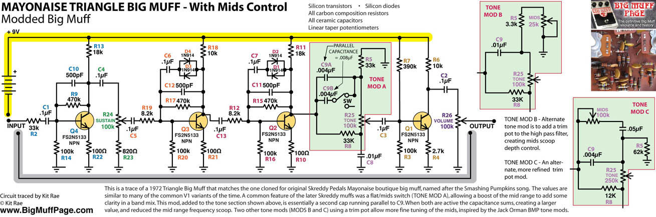
Back to rheostats and where they make a difference. Take a look at the humble Muff Tone control (graphic courtesy of Coda's website):
The resistors R5 and R8 are each forming a respective voltage divider in conjunction with the Tone Pot — add in the caps and you've got very different functions namely the HPF and LPF. Let's mod out that R5 above with the AMZ Presence Control...
R5 is now in series with a 25k rheostat, so it still doesn't matter whether the 3k3 is before or after the rheostat, but in relation to C9 (12n) the flow matters — swap C9 and the 28k3 R5 collective and you've got another LPF in addition to the one formed by 39k and 10n (R8/C8).
Kit Rae has the AMZ version and another mids mod in this schematic on his site:
I tend to go overboard with examples...
I assure you it's only myself I'm flogging, to reinforce within me what I've learned to regurgitate in hopes I'll actually truly assimilate the knowledge and not have to relearn it later.
Like when ...
I re-read "Secret Life of Pots", I've learned more elsewhere and that helps me gain deeper knowledge and meaning each time
I re-read "Secret Life of Pots"... is there an echo in here?
After first starting building, you've already accomplished more in two months than it took me two years to achieve.
@Feral Feline Whoa! No, no, this is not overkill at all - since I'm trying to learn ALL of this VERY quickly, every single example and way of explaining things makes a difference. This is great!!
It'll take me a sec to fully process, but I'm already getting the gist of what you're saying - I kind of forgot that it doesn't matter which way you install a resistor, so why would it really matter which way you plopped in a pot+resistor? Other than CW/CCW rotation preference...
I think the matter of signal flow is something that will click once I understand the flow of actual schematics more. I'm still not quite there, and the last time I tried to plot a schematic on a breadboard I evidently killed an LED! Ha...
For example, take our beloved Baron Samedi - The 470k resistor that becomes the DEATH control inspired me to try that on my (already modded) Executive. I had already replaced the 18k R5 resistor with a 100k pot (+1k resistor) to starve the overall voltage. Works great, helps create the low octave. I take it that's essentially what the BURIAL knob is on the BS, since it also controls the amount of low octave. The DEATH control seems more of a transistor bias knob, and looking at the Executive schematic (and the board itself, below) it seemed likely that R3, one of the 560k resistors, was biasing Q2.
Well, I think I was wrong! I tried replacing it with a 500k pot + 1k resistor, and... it was pretty interesting, but didn't get close to that pinched, gated sound that DEATH gets you on the BS. It kind of just acted like a second BURIAL control. It was cool, but not what I was going for. I thought about trying the same thing for R2, but I'm not sure that's the ticket either. How the heck do I add a transistor bias to this thing? I have a Trumpeter to build (I know, Bosstone overload) and want to add it there as well (since it already has a voltage starve).
I appreciate the kind words, I have NO background in electrical circuits and I'm starting from scratch. I feel like a moron, but at least I'm building functioning pedals! Ha... It's sinking in little by little. The encouragement and info I receive here is absolutely vital, and I would NOT be able to do what I've done so far without you and a handful of others here. Finding PedalPCB has had a huge impact. Hugely appreciative.
R4 looks like it's biasing Q1, I think R2 helps bias/add stability, but monkeying with that one may upset the rest of the circuit too much — I don't know. You will NOT achieve "Death" with the Executive fuzz on its own. Compare the schematics Baron vs Exec and you'll see the Baron has an extra transistor stage tacked on at the end and that's where the Death control is to be found. You could add the MuffinCrumb I mentioned previously to the Executive and then you'll have BS (without the tone control) and you can then add in the Death control.
Check out Electrosmash, good info and analysis that goes a long way to explaining what does what. Extrapolate the info found there to whatever you're working on. Example, lessons learned from studying the Fuzz Face will help make sense of the Bosstone.
The Fuzz Face is a distortion guitar pedal designed in London by Arbitrer Electronics Ltd in the autumn of 1966. This analysis covers the first Arbitrer Fuzz Face model equipped with PNP germanium transistors from the first releases.
Ahhhhhh I see. THAT's where the Muffin Crumb comes in, I don't know how I overlooked that - the Baron has three transistors, and that's obviously key to it's sound. The specifics of how to add a little Muffin Crumb board to the end of an existing board aren't clear, but it's something I'll look at and try to figure out. I assume the resistor I'd have to replace with a pot to achieve DEATH would be on the Muffin Crumb board as well.
I'll check out that Electrosmash link and see what that might clear up too. I appreciate you taking the time to help, and hopefully I can somehow repay the favor one day!
Edit: hoo boy looks like the Muffin Crumb Amplifier Stage really leaves a lot up to the builder- there are three uses (Preamp, Clipping, or Tone Recovery Stages) and no part values! Ha… I’d be pretty lost at sea. I assume in this situation I’d want the Clipping Stage mode, since the BS has several diodes as well as the extra transistor. Other than that (which may be wrong) I’m scratchin my head. Aside from part values, I’m not sure where this would connect to a PPCB board and how off-board wiring would work in that situation. It looks VERY useful, though. Eager to understand it.