SOLVED Clipping ain’t easy.

PAGOON

Active member
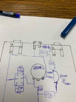
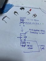
I put this pedal together and I’m trying lower the volume on the other side of the the switch I must have desoldered dozens of options I found a few other options besides a 1n914 and 1n34a… I like the sound of a 2n7000 with a D9e/1n34a … can someone check my sketch? I think it’s right… but it’s wicked loud so is everything I try besides a 1n34a and 1n914… I like the red led with a 1N914 diode to… but for some reason what ever I put on the other end of this on/on switch is crazy loud is there a way to make it as quiet as the 1n34a/1n914 clipping?
 

Attachments

  • image.jpg
    image.jpg
    817.3 KB · Views: 19
  • image.jpg
    image.jpg
    531 KB · Views: 19
Last edited:
Run a large resistor to ground after theouder clippers. You'll have to experiment. Good thing about point to point is you can easily use alligator clips.

Another option would be to double up your 914/34As in series and use a larger output volume pot.
Either way, you want to match the output of each stage, either by bleeding signal to ground or getting the forward voltages of the clipper similar.
.are these hard clipping to ground?
 
Yes hard clipping to ground..i was thinking of putting a 10k resistor in series with one or two red leds. But I will put the 10k on the ground side I’d really like to use the one with a diode and mosfet sounded great… yeah I’m using a b100k pot of I did a 250 or 500k the. It would throw of the other side of the switching which is fine… I will keep playing around I do have some homemade gator jumpers. I can’t believe that never crossed my mind… thanks
 
Last edited:
Okay. So, resistor in parallel with whichever option is louder. I would just clip it in... Hopefully it wont mess with the next stage impedance or create a RC filter.
Not sure what your circuit is...
 
It’s like the copper clad fuzz but I changed a few things so it’s brighter … I think I did the mosfet wrong I tied the Source and gate together and I have to look into that … I don’t think that’s right but it sounded good just loud… hahaha
 
Last edited:
I did do that section a little differently the 47k is supposed to to connect right after the 100r then the 100uf and 100nf to ground..I’m not sure if it would matter.
 

Attachments

  • image.jpg
    image.jpg
    595.7 KB · Views: 6
  • image.jpg
    image.jpg
    483 KB · Views: 6
I used a resistor started at 10k then 36k then 100k 150k 220k and then 470k it didn’t change a thing I built this mosfet clipper and was using the gator clips putting the resistor to the ground on the switch maybe the switch is open due to the thousands of times I have soldered different cliping diodes to them…maybe I will try putting the resistor before the ground and and before the mosfet clipboard I made..
 

Attachments

  • IMG_6792.jpeg
    IMG_6792.jpeg
    65.7 KB · Views: 3
I May just give up and use a different germanium diode with a different voltage with a different silicon diode. But I don’t want to do that I want a different two completely different clipping options. I put a 4.7 capacitor in there and it cranked up the bass … I think i need a good Prototype board bad.
 
Thank you jwin615 for your help… as suspected the switch got roached from all of the de soldering I was doing so it was loud because it wasn’t clipping.. but I still didn’t 100% do what I wanted to do but next time I will have to use a breadboard.
 
Back
Top