
DSV
Member
Hello everyone,
A friend recently reached out and asked if I could clone the Ampeg SS-150 preamp for him.
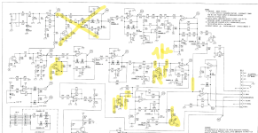
I found the schematic of the SS-70 (the combo version) which sports the exact same preamp as the SS-150, just a lower wattage power amp.
pic1

The preamp has two channels and jfets to switch between the channels. There is also a reverb which I would like to completely omit.
Basically I would just like to clone channel A, without the reverb.
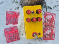
In my design the bipolar 15V voltage is provided by a tracco 2-0923.
Since I am no electronics expert , my first challenge was how to remove jfets (and perhaps components around them) . I cross-checked with the AION FX "VH Drive channel" which is a clone of the Ampef VH140, as there are some similarities between the two circuits. Second challenge is skipping the reverb part of the circuit.
Pic2

Comparing between factory schematics of the VH140 and the AION schematic I would need to remove the marked components. C35+C36 become 1u.
FX send (section around IC5B) is connected to FX return (section around IC6A) , then AION adds a 2,2 uf cap and a 100k resistor to finish the circuit.
pic3

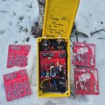
Ok, after making similar adjustments my circuit would be like this.

Which components I took away in my circuit (pic1 factory schematic numbering Q1, C6, R9, R7, Q2, R13, R14, C9, Q3, R22, R95 C18+C19 become 1uF )
Any obvious mistakes / suggestions ? I have left the 100k (R7 in my circuit) as is. Should I perhaps connect c5 directly to ground and omit it ?
I have not had good experience with breadboarding in the past. And considering this is a hi gain circuit I'd like to avoid breadboarding all together.
I will probably design a PCB directly.
A friend recently reached out and asked if I could clone the Ampeg SS-150 preamp for him.
I found the schematic of the SS-70 (the combo version) which sports the exact same preamp as the SS-150, just a lower wattage power amp.
pic1

The preamp has two channels and jfets to switch between the channels. There is also a reverb which I would like to completely omit.
Basically I would just like to clone channel A, without the reverb.
In my design the bipolar 15V voltage is provided by a tracco 2-0923.
Since I am no electronics expert , my first challenge was how to remove jfets (and perhaps components around them) . I cross-checked with the AION FX "VH Drive channel" which is a clone of the Ampef VH140, as there are some similarities between the two circuits. Second challenge is skipping the reverb part of the circuit.
Pic2

Comparing between factory schematics of the VH140 and the AION schematic I would need to remove the marked components. C35+C36 become 1u.
FX send (section around IC5B) is connected to FX return (section around IC6A) , then AION adds a 2,2 uf cap and a 100k resistor to finish the circuit.
pic3

Ok, after making similar adjustments my circuit would be like this.

Which components I took away in my circuit (pic1 factory schematic numbering Q1, C6, R9, R7, Q2, R13, R14, C9, Q3, R22, R95 C18+C19 become 1uF )
Any obvious mistakes / suggestions ? I have left the 100k (R7 in my circuit) as is. Should I perhaps connect c5 directly to ground and omit it ?
I have not had good experience with breadboarding in the past. And considering this is a hi gain circuit I'd like to avoid breadboarding all together.
I will probably design a PCB directly.
 Do share your progress!
")

 The SS-140C has been on my to-do list for a couple of months now, but unlike you I'm a lazy slob so I got nothing so far except for LTSpice simulations.