falco_femoralis
Well-known member
It says Rotary Chorus and as we all know it's hard to find a DIY rotary pedal so I was like

The build doc said it needs a 1590bbs enclosure but after staring at the pics for a while I realized it didn't.
Here's the build doc
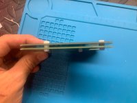
On page 6 you can see the photo of the builder holding the completed sandwiched circuit boards. Note the 3mm nylon standoffs used to separate the two boards. What I did instead is took a leaf out of boss's book and trimmed the leads on the backs of the boards super short with a nice pair of cutters and then used a plastic sheet separator, like they do for the backs of their enclosures.
I think that will work. It's double layer and the boards are not pressed together with force - just enough to get them snug.
Back to our friend good old page 6 of the build doc, also notice the head of the machine screw shrewdly placed underneath the potentiometer. We can omit that and gain another 2mm of vertical space.
Actually we can omit all the fasteners. After this I installed the headers to connect the boards and trimmed them flush with the top board so they would not interfere with one of the pots. In the pic above I don't have pot plastics but I ended up installing them to prevent shorts. If you've ever looked closely at a pot dust cap you'll notice there is a small gap between the bottom of the pot and the inside of the bottom of the cap. I trimmed the part of the cap that sits under the leads to close that gap. That's another mm.
Next step is the placement of the jacks. Venerable page 6 of the build doc contains another image to show how to place the audio jacks.
But we abhor these style audio jacks. They are too big and bulky and don't offer great placement and limit options. Checking the data sheets and comparing measurements, there's another kind of jack we can use and gain another 6mm or so.
That looks like a good time. Notice the bottom edge of the jack is in plane with the circuit board and the top leaves enough room for the back of the enclosure to fit.
There are some extra holes - this was a test enclosure
The smaller size of these jacks also allows me to get the jacks closer to either side of the back of the enclosure, making more room for audio cables that might not be low profile.
Placing the power jack up here also keeps things clean once you start plugging cables in
I used hot glue to keep the wires away from the plugs
A little messy but it works. In the final build I'll come back and tuck the wires in. I used mostly tantalum caps and some low profile electrolytics. These 20 turn trimmers are annoying - 5 turns would have been perfect.
Today my small bear order finally came in and I installed the NE571 and tried out the pedal. After spending some time tuning it I got it to work and it sounds alright! The Delay control is interesting, and it has a different kind of chorus sound from a CE-2
I put it together and did testing in this enclosure so it's quick and dirty. I like big knobs so I put them like this. The LED is super bright because I forgot to add a trimmer to bring it down!
Here's the enclosure I made for it. Now that I've confirmed the pedal works I feel okay drilling it out. I'm waiting on some different knobs to put it all together.
.jpg")
My thoughts... the board could have been laid out better. It seems there wasn't much of a "big picture" way of thinking when the designer came up with the board or the build doc. Check out some of the posts online about how the boards are meant to be connected together. I don't mind the 1590bb format but it would have been nice if the boards were condensed into one and didn't extend under the pots. I'd like to move onto PCB design soonish and this is a prime candidate for a remap. That being said, there is no clock tick.
I'll follow up in a few days once my knobs come in with the completed pedal. I bought the PCB back before the tariffs kicked in so I'm excited to finally see progress!

The build doc said it needs a 1590bbs enclosure but after staring at the pics for a while I realized it didn't.
Here's the build doc
On page 6 you can see the photo of the builder holding the completed sandwiched circuit boards. Note the 3mm nylon standoffs used to separate the two boards. What I did instead is took a leaf out of boss's book and trimmed the leads on the backs of the boards super short with a nice pair of cutters and then used a plastic sheet separator, like they do for the backs of their enclosures.

I think that will work. It's double layer and the boards are not pressed together with force - just enough to get them snug.

Back to our friend good old page 6 of the build doc, also notice the head of the machine screw shrewdly placed underneath the potentiometer. We can omit that and gain another 2mm of vertical space.
Actually we can omit all the fasteners. After this I installed the headers to connect the boards and trimmed them flush with the top board so they would not interfere with one of the pots. In the pic above I don't have pot plastics but I ended up installing them to prevent shorts. If you've ever looked closely at a pot dust cap you'll notice there is a small gap between the bottom of the pot and the inside of the bottom of the cap. I trimmed the part of the cap that sits under the leads to close that gap. That's another mm.

Next step is the placement of the jacks. Venerable page 6 of the build doc contains another image to show how to place the audio jacks.

But we abhor these style audio jacks. They are too big and bulky and don't offer great placement and limit options. Checking the data sheets and comparing measurements, there's another kind of jack we can use and gain another 6mm or so.
That looks like a good time. Notice the bottom edge of the jack is in plane with the circuit board and the top leaves enough room for the back of the enclosure to fit.

There are some extra holes - this was a test enclosure
The smaller size of these jacks also allows me to get the jacks closer to either side of the back of the enclosure, making more room for audio cables that might not be low profile.
Placing the power jack up here also keeps things clean once you start plugging cables in

I used hot glue to keep the wires away from the plugs


A little messy but it works. In the final build I'll come back and tuck the wires in. I used mostly tantalum caps and some low profile electrolytics. These 20 turn trimmers are annoying - 5 turns would have been perfect.

Today my small bear order finally came in and I installed the NE571 and tried out the pedal. After spending some time tuning it I got it to work and it sounds alright! The Delay control is interesting, and it has a different kind of chorus sound from a CE-2
I put it together and did testing in this enclosure so it's quick and dirty. I like big knobs so I put them like this. The LED is super bright because I forgot to add a trimmer to bring it down!

Here's the enclosure I made for it. Now that I've confirmed the pedal works I feel okay drilling it out. I'm waiting on some different knobs to put it all together.
.jpg")
My thoughts... the board could have been laid out better. It seems there wasn't much of a "big picture" way of thinking when the designer came up with the board or the build doc. Check out some of the posts online about how the boards are meant to be connected together. I don't mind the 1590bb format but it would have been nice if the boards were condensed into one and didn't extend under the pots. I'd like to move onto PCB design soonish and this is a prime candidate for a remap. That being said, there is no clock tick.
I'll follow up in a few days once my knobs come in with the completed pedal. I bought the PCB back before the tariffs kicked in so I'm excited to finally see progress!
")