wintercept
Well-known member
Hi all. I was scrolling through Small Bear’s clearance sale and noticed that they’re PCBs are pretty well discounted.
I want to take a crack at the Bear Boost Plus, but I can’t find info on it aside from the write up from Steve at Small Bear found here. However, it’s missing some crucial info. So here’s what I need:
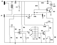
1) What are the capacitors, C4-C9 actually supposed to be? The layout in the article just says “390pF to .0068mF” for these caps, which are switched between with a 6 way rotary switch. There’s a lot of options in that range. I’ve calc’d the high pass filter with different values (with the 120k resistor), and found that 390pF, 680pF, 1nF, 2.2nF, 4.7nF, and 6.8nF would give a decent range of options. I would love to know what values actually came with the kit.
2) How am I supposed to power this thing with the external adapter? The way the schematic shows it:
It just doesn’t make sense to me. It looks like it needs a -9V adapter. I’m fine with whatever, I just need to know for certain. I would prefer to not use batteries.
3) Finally, does anyone have the PDF for the instructions for the kit? The article includes a link for it, but it’s dead. It would probably answer most of my questions. Anything about this would be great, like pictures of paper instructions that might have come with the kit, or even anecdotes.
I know this build is weird, but it has some interesting oddities (P-channel JFET?!, germanium?!, DPDT switching with LED that uses a darlington and a 100Meg resistor?!) Yup... but I think I can handle it. Any info on this would be much appreciated.
I want to take a crack at the Bear Boost Plus, but I can’t find info on it aside from the write up from Steve at Small Bear found here. However, it’s missing some crucial info. So here’s what I need:
1) What are the capacitors, C4-C9 actually supposed to be? The layout in the article just says “390pF to .0068mF” for these caps, which are switched between with a 6 way rotary switch. There’s a lot of options in that range. I’ve calc’d the high pass filter with different values (with the 120k resistor), and found that 390pF, 680pF, 1nF, 2.2nF, 4.7nF, and 6.8nF would give a decent range of options. I would love to know what values actually came with the kit.
2) How am I supposed to power this thing with the external adapter? The way the schematic shows it:

It just doesn’t make sense to me. It looks like it needs a -9V adapter. I’m fine with whatever, I just need to know for certain. I would prefer to not use batteries.
3) Finally, does anyone have the PDF for the instructions for the kit? The article includes a link for it, but it’s dead. It would probably answer most of my questions. Anything about this would be great, like pictures of paper instructions that might have come with the kit, or even anecdotes.
I know this build is weird, but it has some interesting oddities (P-channel JFET?!, germanium?!, DPDT switching with LED that uses a darlington and a 100Meg resistor?!) Yup... but I think I can handle it. Any info on this would be much appreciated.
