Cybercow
Well-known member
Stereophonic Gizmotronic Symphonic Harmonic Perambulator Plus! (Rack-Mount Version)
A few years ago I took on a custom project for a studio in Louisiana. It was far more work that I ever anticipated. But was able to complete it and the testing of it blew me away. The word “lush” does not even come close to what this thing sounds like.

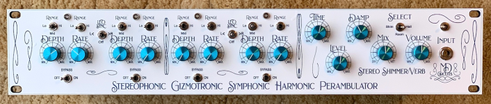
This rack-mounted version of my Stereophonic Gizmotronic Symphonic Harmonic Perambulator is comprised of four modified Small Clone chorus circuits (ala GuitarPCB "Mini-Me") and two Spin-Semi FV-1 based digital shimmer reverb circuits (ala PedalPCB 'Pythagorus' platform). Two each of the chorus circuits are wired serially in pairs to create one channel (Left or Right). Each chorus is wired to independently alter their respective “Depth” and “Rate” settings. Each pair is wired in series with independent LFO (rate controls) – but, can use one or the other LFO in the channel pair as the “Master LFO”. Each chorus in a channel pair can also run their LFO independently.
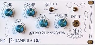
Each chorus serial-pair feeds serially into one of the FV-1 reverb circuits. The FV-1 reverb circuits provide three unique reverb patches – Shimmer, Room and Hall; with “Time” (Ctrl1), “Damp” (Ctrl2) and “Level” (Ctrl3) controls. The “Mix” and “Volume” controls are master controls for the entirety of the circuit.
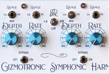
In the center position (Off), the LFO Sync allows each chorus in a pair to run the rate of modulation independently. In the left (L<) position, the “Rate” and “Rate Range” controls of the modulation rate of the Left side of a chorus pair determine the modulation rate of both choruses in the pair. Alternatively, in the right (>R) position, the “Rate” and “Rate Range” controls of the modulation rate of the Right side of a chorus pair determine the modulation rate of both choruses in the pair.
Each chorus circuit can be independently engaged of bypassed. In the “Off” position, the selected chorus is ‘bypassed’. In the “On” position, the chorus circuit is actively engaged and in the signal path.
The “Depth Range” toggle switch provides a “Lo”, “Mid” & “Hi” depth range for each chorus circuit.
The “Rate Range” toggle switch provides a “Lo” & “Hi” rate range control. The “Lo” setting is about 1⁄2 the rate of the “Hi” setting.

The “Depth” and “Rate” control knobs are for incrementally setting their respective designations.
——
The three reverb patches available are: “Shimmer”, “Room” and “Hall”. Each share a “Time”, “Damp” (or ‘filter’) frequency. And the “Level” control determines the amount of reverb.
The “Volume” control acts as a ‘master volume’ for the entire unit.

The “Mix” control provides the balance between the signal coming into the reverb section and the reverb. When all the chorus circuits are bypassed, the signal coming into the reverb is completely dry. And when the “Mix” control is fully counter-clockwise, with all the choruses bypassed, there is only the dry signal passing thru the unit. So, with all the choruses turned off (in bypass), the “Mix” control will only provide the currently selected reverb patch effect by turning it clockwise.
Alternatively, with the “Mix” control fully clockwise, the selected reverb patch will be prominent and the dry (chorus) signal will be buried within the selected reverb settings and “Level” set of controls. The reverb patch is chosen with the “Select” toggle switch. The “Time” control sets the length of reverb time. The “Damp” (filter) control sets the strength of dampening or low pass filter.
The cover artwork on the front panel is 1.5mm plastic plate that was fabricated by @amplifyfun for me from a Photoshop file I created.
And then there's the circuit porn . . . .


Hand drilling stainless steel is a PITA . . . .


Yeah, those cuts are all rough, but the connectors and other hardware do nice job of covering up.
To summarize, the client was more than happy. He wanted me to build some more for a couple of his friends, but after going thru all it took, (it took over three months to build), I decided NOT to do any more rack units. This was way more rewarding than I thought it would be, but too much work for this old fart.
I wanted to share this project build report for the PPCB boards used in it. The client has since sold the unit (unfortunately for financial reasons) and to this day I kick myself for not doing even a rudimentary demo of this unit. It is now a one-of-kind, out there in the wild.
A few years ago I took on a custom project for a studio in Louisiana. It was far more work that I ever anticipated. But was able to complete it and the testing of it blew me away. The word “lush” does not even come close to what this thing sounds like.

This rack-mounted version of my Stereophonic Gizmotronic Symphonic Harmonic Perambulator is comprised of four modified Small Clone chorus circuits (ala GuitarPCB "Mini-Me") and two Spin-Semi FV-1 based digital shimmer reverb circuits (ala PedalPCB 'Pythagorus' platform). Two each of the chorus circuits are wired serially in pairs to create one channel (Left or Right). Each chorus is wired to independently alter their respective “Depth” and “Rate” settings. Each pair is wired in series with independent LFO (rate controls) – but, can use one or the other LFO in the channel pair as the “Master LFO”. Each chorus in a channel pair can also run their LFO independently.
Each chorus serial-pair feeds serially into one of the FV-1 reverb circuits. The FV-1 reverb circuits provide three unique reverb patches – Shimmer, Room and Hall; with “Time” (Ctrl1), “Damp” (Ctrl2) and “Level” (Ctrl3) controls. The “Mix” and “Volume” controls are master controls for the entirety of the circuit.
In the center position (Off), the LFO Sync allows each chorus in a pair to run the rate of modulation independently. In the left (L<) position, the “Rate” and “Rate Range” controls of the modulation rate of the Left side of a chorus pair determine the modulation rate of both choruses in the pair. Alternatively, in the right (>R) position, the “Rate” and “Rate Range” controls of the modulation rate of the Right side of a chorus pair determine the modulation rate of both choruses in the pair.
Each chorus circuit can be independently engaged of bypassed. In the “Off” position, the selected chorus is ‘bypassed’. In the “On” position, the chorus circuit is actively engaged and in the signal path.
The “Depth Range” toggle switch provides a “Lo”, “Mid” & “Hi” depth range for each chorus circuit.
The “Rate Range” toggle switch provides a “Lo” & “Hi” rate range control. The “Lo” setting is about 1⁄2 the rate of the “Hi” setting.
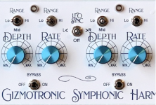
The “Depth” and “Rate” control knobs are for incrementally setting their respective designations.
——
The three reverb patches available are: “Shimmer”, “Room” and “Hall”. Each share a “Time”, “Damp” (or ‘filter’) frequency. And the “Level” control determines the amount of reverb.
The “Volume” control acts as a ‘master volume’ for the entire unit.
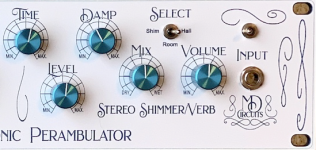
The “Mix” control provides the balance between the signal coming into the reverb section and the reverb. When all the chorus circuits are bypassed, the signal coming into the reverb is completely dry. And when the “Mix” control is fully counter-clockwise, with all the choruses bypassed, there is only the dry signal passing thru the unit. So, with all the choruses turned off (in bypass), the “Mix” control will only provide the currently selected reverb patch effect by turning it clockwise.
Alternatively, with the “Mix” control fully clockwise, the selected reverb patch will be prominent and the dry (chorus) signal will be buried within the selected reverb settings and “Level” set of controls. The reverb patch is chosen with the “Select” toggle switch. The “Time” control sets the length of reverb time. The “Damp” (filter) control sets the strength of dampening or low pass filter.
The cover artwork on the front panel is 1.5mm plastic plate that was fabricated by @amplifyfun for me from a Photoshop file I created.
And then there's the circuit porn . . . .
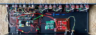
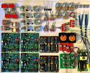
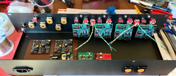
Hand drilling stainless steel is a PITA . . . .
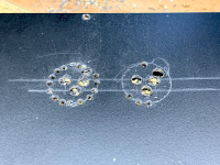
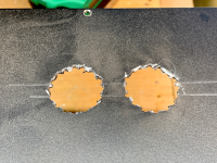
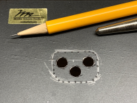
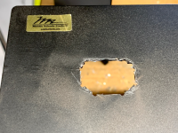
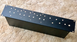
Yeah, those cuts are all rough, but the connectors and other hardware do nice job of covering up.
To summarize, the client was more than happy. He wanted me to build some more for a couple of his friends, but after going thru all it took, (it took over three months to build), I decided NOT to do any more rack units. This was way more rewarding than I thought it would be, but too much work for this old fart.
I wanted to share this project build report for the PPCB boards used in it. The client has since sold the unit (unfortunately for financial reasons) and to this day I kick myself for not doing even a rudimentary demo of this unit. It is now a one-of-kind, out there in the wild.
Attachments
Last edited: