Dumbloid (Special Overdrive PCB) - Switchable Clipping Diodes

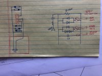
I want to implement a switch to allow for a couple extra clipping options in the feedback loop. I'm not a fan of the stock op-amp clipping. Can someone take a look at what I've drawn up here and give me a sanity check - does it make sense? Is there another way to do this that you would recommend? Any ideas as to what kinds of diodes to try out? I'm going to socket these so I can swap in and out.

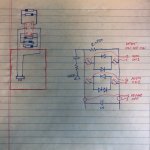
Diode Wiring.JPG
 
I want to implement a switch to allow for a couple extra clipping options in the feedback loop. I'm not a fan of the stock op-amp clipping. Can someone take a look at what I've drawn up here and give me a sanity check - does it make sense? Is there another way to do this that you would recommend? Any ideas as to what kinds of diodes to try out? I'm going to socket these so I can swap in and out.

View attachment 13681
Maybe the best option is to move your LED & use that for your toggle switch ???
 
Looks good to me, ARE 1N4148 your choice of Diodes?
Your leaving C5 & soldering lead to each pad from solder side I Believe?
Thank you! I was going to play around with different diodes I've got a bunch from different builds. This may be a dumb question but are there different diodes that are better for different kinds of clipping? Pretty much everything I've seen so far uses either germanium or Schottky, what about Zener?

And yes the plan was to solder leads to the solder side of C5.
 
If the pedal has plenty of Volume on tap in stock mode, you have a lot more options.
Led's being the Loudest to bat41's being the at the other end of the scale.
1N4148's being the most common being in the Middle so to speak.
 
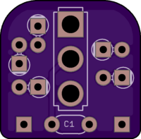
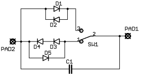
You can do it with a SPDT. I created a little breakout board for that and shared it on OSHpark. You can order the PCB there. Takes about 10 days to get it, depending on how far you are from Portland, Ore.

How it works: Remove the feedback capacitor from the pedal circuit and solder it to C1 on this breakout. Populate the diodes. Wire the two pads on this breakout to the pads for the feedback cap on the pedal PCB.

6e05ad866c42d246e4673d35e3239f6b.png

SPDT diode witch.png
 
You can do it with a SPDT. I created a little breakout board for that and shared it on OSHpark. You can order the PCB there. Takes about 10 days to get it, depending on how far you are from Portland, Ore.

How it works: Remove the feedback capacitor from the pedal circuit and solder it to C1 on this breakout. Populate the diodes. Wire the two pads on this breakout to the pads for the feedback cap on the pedal PCB.

6e05ad866c42d246e4673d35e3239f6b.png

View attachment 13684
Thank you! I'm going to give it a shot without a PCB, hopefully I can get it to work haha. I was thinking I had to cut off both sides of the diodes from the circuit, but forgot that cutting off just one side means there is no current (duh) so yes definitely can do it with an SPDT on-off-on. So that would look like this?
IMG_2717.JPG
 
If the pedal has plenty of Volume on tap in stock mode, you have a lot more options.
Led's being the Loudest to bat41's being the at the other end of the scale.
1N4148's being the most common being in the Middle so to speak.
Gotcha - yea it's stupid loud already, I'll play around with some different diodes then, thanks!
 
  • Like
Reactions: fig
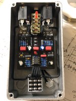
Alrighty I made a switchable op-amp/symmetric/asymmetric clipping selector with some strip board and bus wire. I went through a bunch of different types of diodes and found that the symmetric LED's have me the closest to the natural pedal sound - while smoothing off the decay of the notes, and then asymmetric I used the 1N5241B Zener diodes and they have a little more compression/distortion which complements this really well. There is a small volume drop going from stock to symmetric, and then a bigger jump from symmetric to asymmetric, but overall I'm really happy with it. Schottky and germanium diodes just didn't have enough volume. Thank you everyone for your help! My first modification.
IMG_2721.JPG
 
Last edited:
You can do it with a SPDT. I created a little breakout board for that and shared it on OSHpark. You can order the PCB there. Takes about 10 days to get it, depending on how far you are from Portland, Ore.

How it works: Remove the feedback capacitor from the pedal circuit and solder it to C1 on this breakout. Populate the diodes. Wire the two pads on this breakout to the pads for the feedback cap on the pedal PCB.

6e05ad866c42d246e4673d35e3239f6b.png

View attachment 13684
I will be doing this modification and was wondering if you could help me locate that feedback capacitor on the pcb. This looks like a great mod!
 
Back
Top