- Build Rating
- 3.00 star(s)
I recently posted a build report for my AionFX Cepheus. I kind of rambled on in that build report, but it turns out I really like it. The only thing I don't like is the mechanical 3PDT switching, as I've become a soft-touch snob. I have various bypass modules, but I'd need to do a custom revision for the Cepheus because it offers a buffered bypass mode (which I want) and also has a couple circuit components on the switch breakout board.
So rather than designing a custom bypass board, I went one better and designed a whole PCB with the circuit and integrated bypass. This is actually the second board I had made. On the first, I tried to get fancy, and made some "enhancements" to the circuit. Of course I made some mistakes that required some "surgery" to correct on the actual build.
So then I made another board revision, going back to basics - keeping the circuit almost as-is, and simply integrating the bypass circuit. However, I managed to screw that up too! The build worked, but had some nasty pops/thumps when switching between engaged and bypass. This didn't require massive surgery like the first board, but more of a little "nip and tuck" to correct. So it's not the beautiful build I was hoping for, but it's good enough, and more importantly, it sounds great.
If you're into a neutral-EQ, edge-of-breakup/light drive with a flexible tone stack, you might want to give this a try. I find it very natural sounding with a great feel. The CC-1 and the higher-gain GC-1 share the same circuit topology, and only differ by a dozen or so component values. So you can build two different drives with the same PCB, either Aion's Cepheus board, or the PCB I made. I'm going to build the GC-1 next.
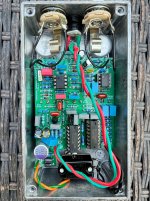
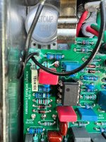
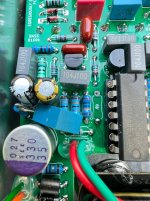
In the pictures, you can see the two "nip and tucks" I had to do. One is the blue capacitor on the lower-left, in-between the big organic polymer cap and the two electrolytics. Originally, that was a single resistor in that spot, but I had to sneak in a series 1uF filter cap. I also had to remove a resistor in that area (R9). And in the upper left, that white 10nF capacitor needed a pulldown resistor added, so you can see how I hacked it in to one of the pot leads. Not pretty, but effective.
I have a few extra boards I'm happy to give away if anyone is interested. The mistakes aren't too hard to work around. This is a buffered electrical bypass design. (If you want to do true bypass, that's on you!)
So rather than designing a custom bypass board, I went one better and designed a whole PCB with the circuit and integrated bypass. This is actually the second board I had made. On the first, I tried to get fancy, and made some "enhancements" to the circuit. Of course I made some mistakes that required some "surgery" to correct on the actual build.
So then I made another board revision, going back to basics - keeping the circuit almost as-is, and simply integrating the bypass circuit. However, I managed to screw that up too! The build worked, but had some nasty pops/thumps when switching between engaged and bypass. This didn't require massive surgery like the first board, but more of a little "nip and tuck" to correct. So it's not the beautiful build I was hoping for, but it's good enough, and more importantly, it sounds great.
If you're into a neutral-EQ, edge-of-breakup/light drive with a flexible tone stack, you might want to give this a try. I find it very natural sounding with a great feel. The CC-1 and the higher-gain GC-1 share the same circuit topology, and only differ by a dozen or so component values. So you can build two different drives with the same PCB, either Aion's Cepheus board, or the PCB I made. I'm going to build the GC-1 next.
In the pictures, you can see the two "nip and tucks" I had to do. One is the blue capacitor on the lower-left, in-between the big organic polymer cap and the two electrolytics. Originally, that was a single resistor in that spot, but I had to sneak in a series 1uF filter cap. I also had to remove a resistor in that area (R9). And in the upper left, that white 10nF capacitor needed a pulldown resistor added, so you can see how I hacked it in to one of the pot leads. Not pretty, but effective.
I have a few extra boards I'm happy to give away if anyone is interested. The mistakes aren't too hard to work around. This is a buffered electrical bypass design. (If you want to do true bypass, that's on you!)