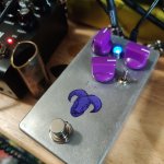
EHX Big Muff (Violet Ram's Head) - first stripboard

uranium_jones

Well-known member
So, over the weekend I just made a Big Muff modeled after the Violet Ram's Head schematic. That may not be so noteworthy, but it is my first time using veroboard, which I wouldn't have even heard of if it weren't for this community and in particular @Chuck D. Bones. This was also the first time I could ever build my circuit using parts I had on hand rather than waiting on a Tayda order. I think that's probably a sign that this is my life now.

layout: http://tagboardeffects.blogspot.com/2012/06/ehx-73-rams-head-big-muff.html
schematic w/ Violet values: http://www.bigmuffpage.com/images/KR_1973_V2_Violet_Schematic_1st_version.jpg
from the page kitrae.net/music/big_muff_history1.html

Here are some of my thoughts about the whole "vero" thing.

Pros:
  • just grab a board and get to work! No waiting on shipping or if a particular PCB is in stock.
  • you get more intimate knowledge of the circuit by having to assemble the whole thing from nothing.
  • Easier to try mods since there are probably extra holes to tie into the circuit.
  • If you are designing your own circuit (someday!) there's no need to learn complicated PCB-making software.
Cons:
  • A lot of time spent on double-checking you're putting the right component in the right spot.
  • far more wires since the potentiometers are not mounted to the board. Not a lot of opportunity to make them shorter the way I did it. Maybe I can work on this in the future to get the box less crowded.
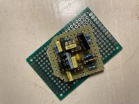
  • the board is "floating" and all the traces are exposed - more potential for shorts. I ended up coating the strip side with old electrical tape.
Conclusion: stripboard really scratches my DIY itch better. More of a pain to troubleshoot (turns out I did not, in fact, ground my I/O instrument jacks, and I wired the volume pot backwards at first.) Sometimes I'll want to do this deep dive, and sometimes I will probably just buy a PCB.

Also, first time I hand-painted a graphic, and used a letter stamp kit for the bare enclosure. Highlights the fact that this was really made from scratch.
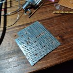
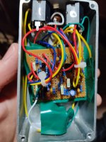
IMG_20210423_222913.jpg

IMG_20210426_215754.jpg

IMG_20210426_234341.jpg
 
Totally agree. Wiring is a PITA, but scratches my DIY itch better. IMO, building from stripboard is much more satisfying since it's truly from scratch. That being said I would definitely use a PCB for the more complicated layouts.

Great job, btw!
 
Looks great!

I really like the "Fresnel" look of the LED.

Vero has its place for sure, though for larger complicated circuits it can get unwieldy and BIG, requiring a larger sized enclosure than for PCB (even perf).

Speaking of which...

Have you tried building on perfboard yet?
 
Looks great!
I really like the "Fresnel" look of the LED.
Vero has its place for sure, though for larger complicated circuits it can get unwieldy and BIG, requiring a larger sized enclosure than for PCB (even perf).
Speaking of which...
Have you tried building on perfboard yet?
Thanks! The LED is a simple 5mm UV led with I think a 4.7K clr.
I've seen a lot of perfboard for sale while I was hunting down vero to try. Do you have any examples of pedals built on perfboard?
 
No pics of my own at the moment.

I did a layout and build of a Modkits "Rock Bottom" — I love the Modkits circuits, they're simple and while I want to do point-to-point turret style at some point, I just can't justify a 2 or 3 transistor circuit taking up so much space — 1590BB for a circuit that fits in a 1590A, AND and and then and then... side jacks with the power routed out the top, further taking up precious pedalboard real-estate.

For a plethora of perf, look at ELS (Effects Layouts by Storyboardist).

I'll try to scrounge up a pic of my Rock Bottom...

PS: I tried to link "ELS", but it didn't take for some reason, here's the full URL: http://effectslayouts.blogspot.com/
 
Last edited:
2918E031-4768-4E8A-9478-5C09E6ADF1BF.jpeg

This was my prototype "Rock Bottom" build for a gift to my friend's daughter, she's a bass-player, too (amongst many instruments).

There's no excuse for having side jacks on a 1590BB enclosure when all it contains is the above components. Why waste 3 sides of an enclosure when one will do? For 1590A, you've got space constraints, you pretty much have to use 3 sides or at least two for jacks & power. However, I did manage to build a boost pedal with 2 stompers, and then 2 knobs and all jacks on one side of the 1590A...
 
Last edited:
One thing you can do with the six thousand pink bubble wrap bags from tayda that you probably have hoarded away in a cubby somewhere is cut them into little squares to insulate the bottom of your vero builds from the enclosure. The sharp ends of the components will snag into the plastic nicely and they stay stuck together quite securely. Works a treat as they say.

Vero is wonderful and fast for most fuzz and OD circuits, but I will say that it's a bit of a PITA when you have more than 3 knobs on the go. The wiring and boxing gets to be a bit of a hassle. It's also great for making little mix-n-match utility boards to keep handy for things like buffers, LPB-1s, tone controls, etc. Fuzz circuit's squealing? grab a little pre-fab Cornish buffer and tuck it in the box and see if that solves the problem.
 
IC meaning transistor? For diodes I used 1N914s, and I think I used 2N5089s for the transistors.
Sorry yes, I meant transistors.

I went with SE4010 on my build. After research, it appeared to be the ‘modern’ replacement of the 2N5133...but I could be wrong.

Also what does the switch do ?
 
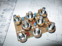
It is possible to build Vero boards with one or more of the pots soldered directly to the board. It's a whole new set of constraints and you might end up having to make cuts between the holes, but it's doable. You've seen my vero builds, so you know what kind of a rat's nest can happen. I use a combination of solid and stranded wire for hookup so the board has support, but is still moveable for ease of assembly & troubleshooting. I use Jimmy Hats on the pots and a layer of packing tape on the inside of the cover for insulation.

For this board, I used long-legged pots and mounted them on the component side. I do not recommend mounting pots on the solder side because the legs can short to adjacent traces and any stress on the legs will pull up the traces.
board 03.jpg
 
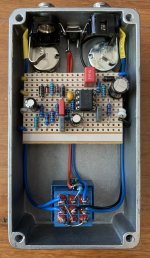
I like Vero simply because it's easy to make up a layout for your own modified designs. And easier to modify - Vero is much more forgiving of resoldering than PCB is. You can often get the wires to leave the board close to the pot it connects to - so for example I like to get all the Gain wires to be up top left of the board, Volume pot wires top right, then tone wiring below those.

GringoD int.JPG

Here you can see that the yellow wires are to the Gain pot, the blue top right goes to the Volume pot, and the white wires go to their respective Bass and Treble pots. Less wire in the box, fewer places to have confusion and shorting. The board sort of sits on top of the tone pots which have their condoms on so no need to insulate the board. The wiring keeps everything in place.

This is one of my most-used pedals. I wouldn't mind having some PCBs to make it but that's waaay out of my league - There's no way I could design a PCB. Vero is easy!
DAMN, that's a neat layout. What gauge wire is that? I'd love to make something so tidy inside!
 
Haha thanks! Gauge of wire? Not 100% certain but I think it's 22. It's from Tayda. The trick is to wire up the box without the board - do everything like the switch, the jacks, the LED etc. Then as you add the wires to the board just look at how long the wire has to be to reach the pot lug or whatever it is and cut it to that length, allowing for the little bit at the end which will be stripped, tinned and soldered. Attach all of the wires to the board then attach it to the parts in the box, start with the top pot connections, then lower pot connections, then everything else. It's all logical and actually not that difficult. I dunno, I just find it fun to make it as neat as I can. :) I love making things. Being neat doesn't necessarily make anything sound better but it is very satisfying.

And it makes it easy to troubleshoot - it's extra obvious what is going where. Sometimes if something doesn't work I'll pick the pedal up and find the problem almost instantly.

Oh, and sorry - definitely didn't mean to hijack your thread. I agree with your post 100% and like to share the love!
 
Back
Top