SOLVED Electric Lover Flanger (Electric Mistress clone from PCBGuitarmania)

Ramandolo

New member
Hello, I'm new here.

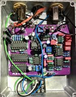
I have achieved this Mistress Flanger clone, it worked fine for a couple of hours, and then, only dry signal is coming out !

I have tried to re-biais and recalibrate it but, only the dry signal comes out !
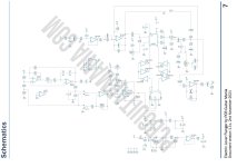
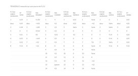
I 've checked all voltages and compared to voltage list: all IC are OK except MN3207 Pin 4 (not MN3007) :

Pin 1 0 V
Pin 2 4,2 V
Pin 3 4,8 V
Pin 4 -0,23 V (negative) !!!??? Should be about 45 mV
Pin 5 8,7 V
Pin 6 4,25 V
Pin 7 4,85 V
Pin 8 4,85 V

I have checked for shorts, chop sticked all components, found no cracklings.
I have swaped all IC's with new ones, Q1 , Q2, changed MN3207 Coolaudio : Still dry signal comes out.

With a probe, I have dry guitar signal entering MN3207 Pin 3 but, no guitar signal comes out from pin 7 and 8.
With probe, found a clock signal on LM324 pin 1, 3 and 14.

With osciloscope, I found a square wave circa 20 Khz on pin 7 and 8 MN3207.

I can't understand why I have a negative voltage on MN3207 pin 4 : could it be a C5 faulty ? Other .. ?
I have no experience with clock pedals.

Thanks for help.
 

Attachments

  • IMG_1712.jpeg
    IMG_1712.jpeg
    751.4 KB · Views: 13
  • Capture d’écran 2024-03-05 à 11.09.59.jpeg
    Capture d’écran 2024-03-05 à 11.09.59.jpeg
    215.6 KB · Views: 14
  • Capture d’écran 2024-03-05 à 11.19.37.jpeg
    Capture d’écran 2024-03-05 à 11.19.37.jpeg
    139.6 KB · Views: 13
Last edited:
There's no proper Vgg voltage on pin 4, and for an MN3207 it should be around +8.4v, not 45mv (when using a 9v supply). The designer didn't include everything needed for the MN3207 to work correctly. Here's how to fix it:

Make R10 a 6.8k resistor. Solder one end of a jumper wire to pin3 of the bias trimmer. Solder the other end to pin4 of the BBD. Assuming everything else is working right you should get output from the MN3207 now.
 
The problem is that you need an mn3007. The building documentation says that it will work with a 3207 but it doesn’t.

I’m not an expert but I had the same problem as you and had t was fixed by using the 3007. Many people on the facebook group had this gap poo en too, it’s a common issue.

Save your 3207 for a nice chorus pedal. The Caesar chorus is a good choice

Edit: or follow Madbean’s advice. He knows what he is talking about and is a legend.
 
Thanks for your answer Bean !!!!! I will try your solution tomorrow and post my results.
Thanks Neilthésal, MN3007 are so hard to find ..

One extra thing: your supply voltage is on pin5 and you are reading 8.7v there, not 9. You want your Vgg voltage on pin4 to be about 0.6v lower than the supply for the MN3207. In that case, you may want to make R10 either 8k2 or 10k instead of 6k8. Or, just socket that resistor and use the value that gets you closest to 8.1v or so on pin4 after you solder the jumper.

What you are doing here is creating a voltage divider with R10 and the Bias trimmer to use as the voltage reference for pin4. That's the part that's missing on the design. Normally this is generated automatically when using an MN3102 clock, but this flanger uses a different circuit for clock.
 
I stopped buying from PCB guitar mania after finding open (or missing?) traces on the last two projects I built. I had to jumper them to get them to work.
I was wondering if I had blown a trace on the last project, so ordered a second pcb on sale. The new pcb had a missing trace.

YMMV
 
Solved !
I have tried to jumper with various resistances pin5 (8,7V) and pin4 of 3207 (didn't touched R10).
Started with 8k2 as discussed but obtained 8,1V with some increments to a 470K resistor.
The pedal works now beautifully !!!!!

Many many thanks Bean.

Cool!

-Edit - I keep mixing things up (deleted what I had here originally). Here's the actual correct info:

For MN320x BBD chips, VGG should be set at 14/15 the value of the supply. So, if it's 9v, then Vgg is 8.4v. Supply limit is 9v on MN320x chips. So, 8.1v is correct for your 8.7v supply on your build.

For MN300x, Vgg is 1/15 the value of the supply. So, 0.6v for 9v supply, 1v for 15v supply. 15v is the limit for MN300x. Additionally, MN300x can be powered by negative DC. In that case it's the same fraction but with a negative sign. So, for really old designs that power the BBD with -15vDC, the correct Vgg is -1v.

Everything you never wanted to know. There's also more stuff about how to easily convert between the two types, but I won't overload you with info.
 
Last edited:
Back
Top