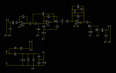
Feedback on schematic for a simplified Op Amp Muff variant

Screen Shot 2023-11-07 at 2.07.30 PM.png

I wanted to simplify the Op Amp Big Muff to bias both op amps at +4.5 and to replace the tone control with a simple shelving filter. I also did slightly asymmetric LED clipping instead of the 4148s.

I got proto boards made and they sort of work... loud, low rumbling noise in the background and most strangely, the Fuzz control behaves weirdly: rolling it back and forth, you can see one or the other clipping LED light up depending on which way you roll it, and the sound cuts out while the pot is moving.

I'm confident that the board is accurate to the schematic and that my soldering isn't the issue. I know just enough to be dangerous at this point so I'm sure I messed something up schematic-wise - if anybody can point out what I may or may not have missed, that would be much appreciated.
 
Last edited:
I've been confused by the R9 resistor when was studying this circuit before. It would make more sense to me for that resistor to go directly to ground instead of running to the 10uf cap connected to 62k resistor there. I've seen schematics where supposedly the 47 connected to ground instead of the capacitor. You might want to try just removing the 47 ohm resistor from the board and seeing how it reacts. I know one of the Keeley op ap fuzzes uses that pot for a variable resistor instead of a voltage divider. That variable resistor adds up with the 8.2k resistor to lower/raise the gain on the clipping section.
 
I've been confused by the R9 resistor when was studying this circuit before. It would make more sense to me for that resistor to go directly to ground instead of running to the 10uf cap connected to 62k resistor there. I've seen schematics where supposedly the 47 connected to ground instead of the capacitor. You might want to try just removing the 47 ohm resistor from the board and seeing how it reacts. I know one of the Keeley op ap fuzzes uses that pot for a variable resistor instead of a voltage divider. That variable resistor adds up with the 8.2k resistor to lower/raise the gain on the clipping section.
I used the Dream Fuzz schematic as reference when I put this together and it has the 47R connected to the capacitor as well - I'm going to assume it's correct but I'll certainly give that a shot.
 
I built a dream fuzz and it worked fine like that too. I'm interested in hearing how that voltage divider setup compares to the variable resistor still.
 
Screen Shot 2023-11-07 at 5.34.38 PM.png Somebody on diystompboxesdrew my attention to C5 on my schematic - looks like at some point in the design phase the wires attached to C5 on the schematic got all flipped around and the polarity of the cap was reversed. I flipped the cap around on my proto board and all is well. Time to fix it and to order new boards...
 
How do you like the new tone control?
It's exactly what I always wanted out of an Op Amp Muff. I exclusively use my EHX reissue in tone bypass mode so that I get the mids back, but I always wished I had a way to soften the treble. This lets me do exactly that - my implementation allows you to variably shelve off highs above around 900Hz. I tuned it just to the point that I felt it rolled off the icepick highs without interfering with the op amp muff "grind".
 
Last edited:
Back
Top