zelcanada
Member
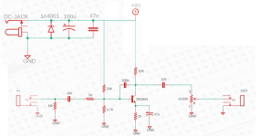
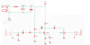
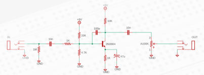
I've been spending a lot of time playing with my breadboard, and now I'm on to the next step: moving a circuit to strip board to make a pedal enclosure! I've downloaded DIY Layout Creator (thanks to some great posts on here!) and picked a simple circuit to start with. I'm using the treble boost circuit from Coppersound's website, because it seems like a fairly simple circuit to start with, and it sounded great on my breadboard:

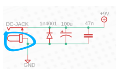
Here's my question though: there was a part of the instructions from Coppersound that talked about power filtering, which seemed important. It gave a little schematic for it:

When designing the stripboard layout, how does this fit into the schematic of the entire circuit...? Is the LED in this diagram my LED for the pedal (to signal on and off)? If so, how do I connect it to the foot switch? If so, shouldn't it have a resistor?
I want to do this properly, and I'm excited to try and do the layout myself... I think I'll be fine with the first schematic, but I want to make sure I'm not forgetting anything when turning my schematic into "reality". I just can't wrap my head around how this power filtering part "connects" with the whole circuit design.
Thanks!
Here's my question though: there was a part of the instructions from Coppersound that talked about power filtering, which seemed important. It gave a little schematic for it:
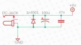
When designing the stripboard layout, how does this fit into the schematic of the entire circuit...? Is the LED in this diagram my LED for the pedal (to signal on and off)? If so, how do I connect it to the foot switch? If so, shouldn't it have a resistor?
I want to do this properly, and I'm excited to try and do the layout myself... I think I'll be fine with the first schematic, but I want to make sure I'm not forgetting anything when turning my schematic into "reality". I just can't wrap my head around how this power filtering part "connects" with the whole circuit design.
Thanks!

