caspercody
Active member
Hello
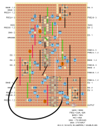
I created a veroboard and made the Furman PQ3, and it worked on the first time powering up. Honestly I was shocked as this is a big board and lots of wiring.
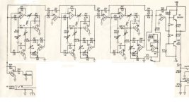
I attached an image of the schematic I used. The input goes directly to pin 3 of the Gain pot, and exactly as shown on the attachment up to Op-amp J. I then have output from pin 7 to the 33uf (C12) and 11k to ground (R74) then output.
I did not add anything else on the schematic after this point.
I have a couple of questions:
What does Op-amp H and beyond do in the schematic (starting at R55 to the output jacks in the schematic)?
Does anyone have a better input and output to use besides the Op-amp H and Op-amp G (input jack and gain pot)?
I created a veroboard and made the Furman PQ3, and it worked on the first time powering up. Honestly I was shocked as this is a big board and lots of wiring.
I attached an image of the schematic I used. The input goes directly to pin 3 of the Gain pot, and exactly as shown on the attachment up to Op-amp J. I then have output from pin 7 to the 33uf (C12) and 11k to ground (R74) then output.
I did not add anything else on the schematic after this point.
I have a couple of questions:
What does Op-amp H and beyond do in the schematic (starting at R55 to the output jacks in the schematic)?
Does anyone have a better input and output to use besides the Op-amp H and Op-amp G (input jack and gain pot)?
")