gtfields13
Well-known member
- Build Rating
- 5.00 star(s)
With my other business (dead espresso machine) out of the way, I am finishing up the pedals that had been waiting for the box-o'-pink goodies that finally arrived from Tayda.
First up, my 2nd Phido Sound pedal, a Fuzz Face built on the PedalPCB Twin Face PCB.

I completely built out the Germanium PNP side on breadboard first, so I could tune resistors as needed to match up with my stash of Soviet germanium. I have measured these a little differently than the RGKeen method, specifically making my measurements at a target voltage and collector current and using trimpots instead of resistors.
My transistors are:
Q1: GT309D (ГТ309Д) measured at 9V supply and Ic of 250µA, showing hFe of 56 and leakage of 15 µA
Q2: GT402D (ГТ402Д) measured at 9V supply and Ic of 500µA, showing hFE of 80 and leakage of 96 µA (also measured hFE 92 by RGKeen method)
With these transistors both a bit lower than the base circuit prefers, I needed to switch R4 to 47K, increasing the feedback for Q1. With this in place, the middle of the bias trimpot gives bias values that hit the standard targets right on the nose (see ElectroSmash, RGKeen or others for the numbers).
I figure to stick with these transistor pairings for additional Fuzz Debates that I will release into the wild. The GT309 doesn't handle a lot of current (hence, Q1 location) but these have really low leakage currents on a consistent basis. The GT402, on the other hand, can handle plenty of power on the output side.
For the silicon, NPN side, I used BC108Bs. I checked out the biases on the PCB, and the normal build doc resistors work perfectly.
My other change was changing C3 from 10 to 22 nF, to push the corner of the output filter down a bit for a bit heavier bass sound (in my imagination, if not perceptive reality).

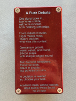
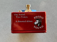
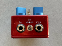
I printed the case at Tayda, and while I generally did better than the my first attempt at printing, I learned more about borders as a result of this latest print job.
I also created my first breakouts for the jacks so I am now using JST connectors for all my interconnects. I am much faster with crimping pins on wires than soldering them to the board.
It's a shame Player Haters is over, because there are some excellent goofs in here. I'll leave those to you to spot, although I will say that I learned on my first ever OSHPark PCB order that putting the Screen Print text on the Solder Mask layer is not a good idea.
I have put together a basic demo showing the two sides of the pedal with progressively more fuzz. I find it curious that there is more noise coming from the silicon circuit than the germanium circuit.
Fuzz Debate #001 Demo
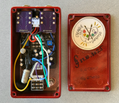
Here's the rest of the case ('cause I like to have a story).


Pedal three is built and tested, I just need to put together the pics and demo next.
First up, my 2nd Phido Sound pedal, a Fuzz Face built on the PedalPCB Twin Face PCB.

I completely built out the Germanium PNP side on breadboard first, so I could tune resistors as needed to match up with my stash of Soviet germanium. I have measured these a little differently than the RGKeen method, specifically making my measurements at a target voltage and collector current and using trimpots instead of resistors.
My transistors are:
Q1: GT309D (ГТ309Д) measured at 9V supply and Ic of 250µA, showing hFe of 56 and leakage of 15 µA
Q2: GT402D (ГТ402Д) measured at 9V supply and Ic of 500µA, showing hFE of 80 and leakage of 96 µA (also measured hFE 92 by RGKeen method)
With these transistors both a bit lower than the base circuit prefers, I needed to switch R4 to 47K, increasing the feedback for Q1. With this in place, the middle of the bias trimpot gives bias values that hit the standard targets right on the nose (see ElectroSmash, RGKeen or others for the numbers).
I figure to stick with these transistor pairings for additional Fuzz Debates that I will release into the wild. The GT309 doesn't handle a lot of current (hence, Q1 location) but these have really low leakage currents on a consistent basis. The GT402, on the other hand, can handle plenty of power on the output side.
For the silicon, NPN side, I used BC108Bs. I checked out the biases on the PCB, and the normal build doc resistors work perfectly.
My other change was changing C3 from 10 to 22 nF, to push the corner of the output filter down a bit for a bit heavier bass sound (in my imagination, if not perceptive reality).
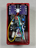
I printed the case at Tayda, and while I generally did better than the my first attempt at printing, I learned more about borders as a result of this latest print job.
I also created my first breakouts for the jacks so I am now using JST connectors for all my interconnects. I am much faster with crimping pins on wires than soldering them to the board.
It's a shame Player Haters is over, because there are some excellent goofs in here. I'll leave those to you to spot, although I will say that I learned on my first ever OSHPark PCB order that putting the Screen Print text on the Solder Mask layer is not a good idea.
I have put together a basic demo showing the two sides of the pedal with progressively more fuzz. I find it curious that there is more noise coming from the silicon circuit than the germanium circuit.
Fuzz Debate #001 Demo
Here's the rest of the case ('cause I like to have a story).
Pedal three is built and tested, I just need to put together the pics and demo next.


