- Build Rating
- 4.00 star(s)
I've really been loving this Effects Layouts Spice Runner (based on the Way Huge Saucy Box) that I built recently. Enough that I felt the circuit deserved my custom PCB treatment. Here I present my "Gigantic Sauce Container".
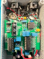
The circuit is interesting in that the drive knob is a dual-gang pot that controls both the amount of overdrive and also acts as a clean blend. The clean circuit is essentially two series Neve 1073 preamps. The clipping circuit starts with a familiar diodes in an opamp feedback loop, but there are three more opamp stages, with some interesting resistor-cap-LED pair-ground constructs; I'm not sure if this is more clipping or some fancy filtering (I have yet to run this with the gain maxed, back cover off, in the dark to see if those LEDs light up at all).
To me, it does the dirty boost to mid-gain thing really well. It's fairly EQ neutral ("transparent") to my ears. It might cut a bit of bass, but I like that, as it keeps it tight when pushing another drive (or presumably would also be great pushing an already overdriven amp). I don't know if it's the clean blend, or just the overall approach to tone-shaping, but it has really great clarity, even at the higher drive settings (though it's definitely not a high-gain drive by any means). It pairs wonderfully with the Hard Rock Pinnacle Purebread Drive (@Chuck D. Bones modified Animals Diamond Peak Hybrid Drive).
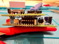
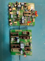
Anyway, the circuit has a lot of components - it's quite literally two independent circuits. So the challenge was to create my own PCB and also use these design elements:
Everything I wanted to do takes up even more board space, and as you can see, even without all that, Effects Layouts used pretty much all available space for the Spice Runner.
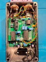
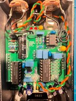
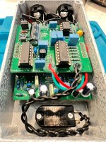
So I put all the non-effect circuitry (polarity protection, power supply, buffer, VREF circuit, bypass) on a separate board and made a stacked design (see the PedalPCB Byzantium Flanger for another design that does this).
Jump to the conclusion: everything works, but I had all kinds of stupid mistakes, cosmetic and ergonomic along the way:
The pin headers don't hold as tight as I'd like. Since gravity will be working against the PCB "sandwich", I was afraid of the boards coming apart over time. To address this, I put some strips of adhesive-backed foam on the backside of the enclosure (this is the same foam that is used for weather stripping around doors and windows). This puts some non-conductive gentle pressure on the two PCBs, and should keep them firmly mated together.
Once I got past all the dumb mistakes and silliness, I spent a little time playing and sanity checking against the Spice Runner. It sounds pretty much identical. Just for kicks, I used BA282 diodes instead of 1n914/1n4148. My circuit also uses half of a TL072 as the buffer, whereas the Spice Runner/Saucy Box has an NPN BJT buffer. I used BC549C transistors for the Neve preamp section, whereas the Spice Runner uses 2n5088. I use a massive 470uF filter cap and 47R series resistor for power supply decoupling and filtering, whereas the Spice Runner uses 100uF and 10R. I used the other half of the TL072 for a VREF buffer, where the Spice Runner just has a cap. All very minor tweaks that I don't think make any meaningful difference.
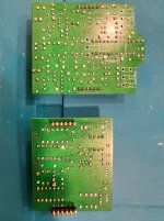
I'm pretty proud of the PCB layouts. I took pictures of the back, because I came quite close to routing everything on the top layer, leaving the bottom layer as a mostly-unbroken ground plane. And I did that without running any traces through IC pins or right next to each other (all traces have at least a trace-width of ground between them).
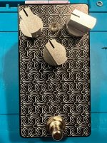
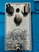
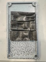
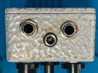
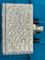
For the artwork, since this is a "sauce"-themed build, I used an aardvark as a homage to Secret Aardvark Hot Sauce. However, the enclosure turned out so poorly, I feel I'm doing a disservice to the greatness that is Secret Aardvark!
When time permits, I'm going to do a second build of this circuit, and put it in the neat-o September 2025 Limited Run enclosure I got from BLMS!
I'm docking myself a star for the ugly aesthetics. But, ultimately, it's about the circuit, and I think that's a success!
The circuit is interesting in that the drive knob is a dual-gang pot that controls both the amount of overdrive and also acts as a clean blend. The clean circuit is essentially two series Neve 1073 preamps. The clipping circuit starts with a familiar diodes in an opamp feedback loop, but there are three more opamp stages, with some interesting resistor-cap-LED pair-ground constructs; I'm not sure if this is more clipping or some fancy filtering (I have yet to run this with the gain maxed, back cover off, in the dark to see if those LEDs light up at all).
To me, it does the dirty boost to mid-gain thing really well. It's fairly EQ neutral ("transparent") to my ears. It might cut a bit of bass, but I like that, as it keeps it tight when pushing another drive (or presumably would also be great pushing an already overdriven amp). I don't know if it's the clean blend, or just the overall approach to tone-shaping, but it has really great clarity, even at the higher drive settings (though it's definitely not a high-gain drive by any means). It pairs wonderfully with the Hard Rock Pinnacle Purebread Drive (@Chuck D. Bones modified Animals Diamond Peak Hybrid Drive).
Anyway, the circuit has a lot of components - it's quite literally two independent circuits. So the challenge was to create my own PCB and also use these design elements:
- Replace electrolytic 1uF capacitors with box film (and right-sized footprints)
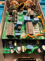
- Use RG Keen's Advanced Power Switching and Polarity Protection for Effects reverse-polarity protection scheme (using the low-RDSon Infineon IRFU5305PBF p-mos)
- Boss-style buffered electrical bypass using a CD4053 as an electrical switch, CD40106 as the footswitch responder, and a plain jane TL072 buffer
Everything I wanted to do takes up even more board space, and as you can see, even without all that, Effects Layouts used pretty much all available space for the Spice Runner.
So I put all the non-effect circuitry (polarity protection, power supply, buffer, VREF circuit, bypass) on a separate board and made a stacked design (see the PedalPCB Byzantium Flanger for another design that does this).
Jump to the conclusion: everything works, but I had all kinds of stupid mistakes, cosmetic and ergonomic along the way:
- You can see in the pictures, I used too much transfer agent for the waterslide decal, which became "caramelized" during the heat soak process; this is the worse-looking enclosure I hinted at in Edit 3 of my Catalinbread Varioboost (Custom PCB) build report
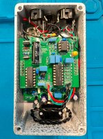
- The lower board needs low profile, and I mean low profile components. The 1uF box caps I have are like 1 or 2mm too tall! I realized they were a bit too tall after the pin headers for both boards had been soldered. I had everything all soldered up, then did a test dry fit - and because of the height of those blue box film caps, the pin headers barely touched, and certainly didn't have enough room to comfortably sink all the way in. So I had to de-solder the top (male) pin headers, and set them lower. Unsoldering pin headers like that is no fun!
- I didn't give myself enough room at the top of the enclosure for anything but those low-profile Lumberg I/O jacks. Originally I soldered in bigger jacks, and they simply don't fit!
- On first power-up, I thought I completely screwed up, because I only got a bit of faint, garbled sound on really hard strums of the guitar. I started probing around with my multimeter, and found that VREF was basically at 0v, and even the main voltage was around 7v (which it should have been right at 9v, if not slightly higher). So I pulled power and split the two boards and started probing: no obvious shorts. Then I mated the boards back together, and still no short. I gave it a second try - everything worked fine! I'm certain that I originally had the mating pin headers improperly aligned. I deliberately put a GND pin between every signal/power pin, so I'm certain now that I was shorting out both power and VREF (hence the 0v VREF and major voltage drop on the 9v rail). In hindsight, I should have "keyed" the mating pins in a such a way to make it very hard to have the boards mis-aligned.
The pin headers don't hold as tight as I'd like. Since gravity will be working against the PCB "sandwich", I was afraid of the boards coming apart over time. To address this, I put some strips of adhesive-backed foam on the backside of the enclosure (this is the same foam that is used for weather stripping around doors and windows). This puts some non-conductive gentle pressure on the two PCBs, and should keep them firmly mated together.
Once I got past all the dumb mistakes and silliness, I spent a little time playing and sanity checking against the Spice Runner. It sounds pretty much identical. Just for kicks, I used BA282 diodes instead of 1n914/1n4148. My circuit also uses half of a TL072 as the buffer, whereas the Spice Runner/Saucy Box has an NPN BJT buffer. I used BC549C transistors for the Neve preamp section, whereas the Spice Runner uses 2n5088. I use a massive 470uF filter cap and 47R series resistor for power supply decoupling and filtering, whereas the Spice Runner uses 100uF and 10R. I used the other half of the TL072 for a VREF buffer, where the Spice Runner just has a cap. All very minor tweaks that I don't think make any meaningful difference.
I'm pretty proud of the PCB layouts. I took pictures of the back, because I came quite close to routing everything on the top layer, leaving the bottom layer as a mostly-unbroken ground plane. And I did that without running any traces through IC pins or right next to each other (all traces have at least a trace-width of ground between them).
For the artwork, since this is a "sauce"-themed build, I used an aardvark as a homage to Secret Aardvark Hot Sauce. However, the enclosure turned out so poorly, I feel I'm doing a disservice to the greatness that is Secret Aardvark!
When time permits, I'm going to do a second build of this circuit, and put it in the neat-o September 2025 Limited Run enclosure I got from BLMS!
I'm docking myself a star for the ugly aesthetics. But, ultimately, it's about the circuit, and I think that's a success!
Attachments
-
 IMG_2087.jpg375.7 KB · Views: 48
 -
 IMG_2086.jpg356.1 KB · Views: 50
 -
 IMG_2085.jpg334.7 KB · Views: 45
 -
 IMG_2084.jpg352.3 KB · Views: 43
 -
 IMG_2080.jpg258.8 KB · Views: 43
 -
 IMG_2079.jpg362 KB · Views: 43
 -
 IMG_2078.jpg388.2 KB · Views: 39
 -
 IMG_2090.jpg386.1 KB · Views: 38
 -
 IMG_2089.jpg300.8 KB · Views: 31
 -
 IMG_2088.jpg262.3 KB · Views: 38