
You are using an out of date browser. It may not display this or other websites correctly.
You should upgrade or use an alternative browser.
You should upgrade or use an alternative browser.
Greengage Overdrive
- Thread starter mmm
- Start date
Feral Feline
Well-known member
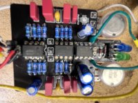
Pic is too blury. Please take another with better focus.
Also, take a pic of the other side of the board, solder side, and all wire connections.
Reflow the solder on IC1's socket and on the the IC100's socket — obviously remove the chips first. Inspect the solder joints with a bright light and strong magnifier.
If something's wrong with IC1, that could lead to the charge pump being overworked, like trying to provide voltage when there's a short under the socket and all/most the power is being dumped to ground.
You've replaced the full chip set and the same thing's happening, so highly likely it IS the soldering or a hidden short somewhere.
Check the power electrolytics: C100, C101, C102 — maybe one of them's a dud right off the manufacturing line (happened to me with brand new spark-plugs once).
I once triple-quadruple checked a non-working breadboard-build of mine against the schematic and couldn't find the problem — then a fresh set of eyes, my friend's, spotted the problem immediately. I had copied out the schematic incorrectly and written 390k when it should've been 390Ω, as soon as I swapped out that resistor for the correct 390Ω, the circuit worked.
Looks like you've socketed the "+ -", up by the D4 clipping diode, you sure you got the power wired up correctly?
Remove the power and then trace the power paths with your DMM set to beep-mode, see if there's a loss of continuity between power in and the caps and protection diode up to the charge pump, but keep going to the IC1's power input.
Pull up all the datasheets for your ICs and charge pump...
I don't know what else to suggest, other than get yet another pair of eyes on it.
MichaelW
Well-known member
Better pictures would definitely be helpful. But from what I can make out the IC's look like legit TI's.
Having said that, Tayda has been known to ship counterfeit chips, one I reason I don't get IC's from them, it's always a risk.
I think we'd need to take a closer and more clear look at your clipping mods too. Looks like you've socketed some of those and are trying some different things.
Having said that, Tayda has been known to ship counterfeit chips, one I reason I don't get IC's from them, it's always a risk.
I think we'd need to take a closer and more clear look at your clipping mods too. Looks like you've socketed some of those and are trying some different things.
mmm
New member
Thx. Spending next few days soldering. Trace. Solder. Replace components per comments. I will update with pic. by Sunday.
Thank you All. I do appreciate. ( Socked question- I read several comments about cap replacements for Bass and socketed all the caps originally) I have scrapped that idea and directly soldered with test before 1st post. - most likely root of problem (bad connection). (will show next post: pic diodes & power connection). Clear photo. Sorry, the fonts above. Cut and past from word.
Thank you All. I do appreciate. ( Socked question- I read several comments about cap replacements for Bass and socketed all the caps originally) I have scrapped that idea and directly soldered with test before 1st post. - most likely root of problem (bad connection). (will show next post: pic diodes & power connection). Clear photo. Sorry, the fonts above. Cut and past from word.
mmm
New member
I burnt my traces. - Put this on hold while finishing other projects. Thank you for the help. I will repost it when completed.
side note, Park and Ride- is done.")
side note, Park and Ride- is done.
mmm
New member
yep destrored the PCB doing stupid things. Bought a new PCB. All is fine. Works great. (if ya donot do stupid things, It works). Thank you for you help.I burnt my traces. - Put this on hold while finishing other projects. Thank you for the help. I will repost it when completed.
side note, Park and Ride- is done.