Guvernator/Aion fx Equinox output mod?

john kurzweg

New member
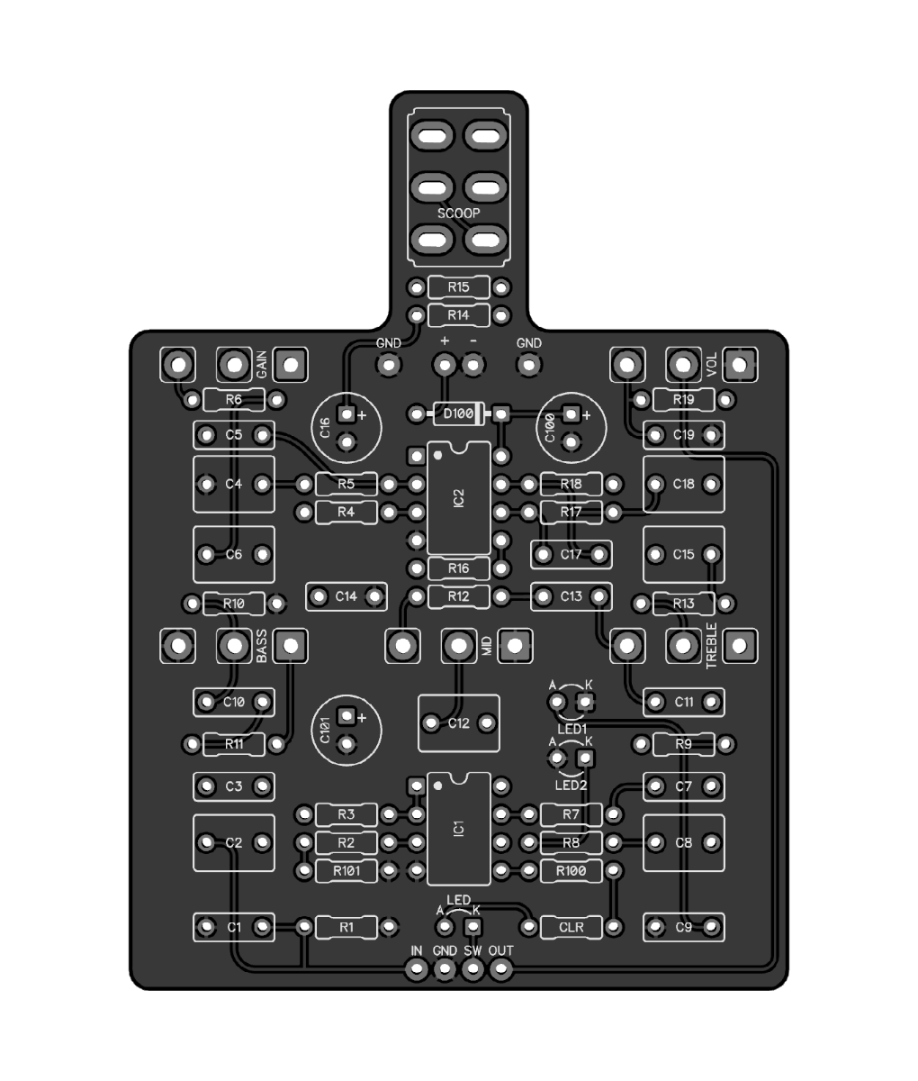
Just finished an Aion fx Equinox (pcb build, not kit - huge victory for this nube!).
Really like the sound of this pedal but I wish there was more output (not gain) — Even in the loudest clipping mode it’s not quite at unity to my ears —and of course it’s even quieter in the other 2 clipping modes.
Are there any simple mods to increase the output? I don’t mind an increase in bass either , I’ve got the volume and low end maxed to “match” the bypass clean sound….
As always, any help is much appreciated —thanks!
 
Last edited:
I don't see a lot of options for simple tweaks to increase output volume without increasing the amount of clipping in this one... both gain stages are in front of the clipping diodes so any increase in gain is going to result in more clipping.

(Just to be clear... an increase in volume technically is gain, and we want that. Not to be confused with clipping or distortion that can result from gain, which we're trying to avoid)

Your best bet might be to add a small boost stage after the Guvnor circuit. There are a couple options in the shop, but you could just as easily whip something up on vero to see how you like it.

Take a look at the schematic for the Flank Distortion (Bombastortion), it's basically a modified Guv'nor with a gain/filter stage on the output.

Thanks for the suggestions - I barely understand electronics , but by looking at the schematic and thinking about the led clipping, I had started to think the same thing, which hopefully means I’m starting to grok the basics….-Again , thx for the quick reply!
 
Like Robert said only little improvements possible. Did you omit C12? This makes it briter and tiny bit louder. If you like the led clipping (middle position) you could a swap with the leds. The reds into D4 and D5, while use blue leds as d2 and d3. Blue leds have higher vf.
 
Last edited:
Like Robert said only little improvements possible. Did you omit C12? This makes it briter and tiny bit louder. If you like the led clipping (middle position) you could a swap with the leds. The reds into D4 and D5, while use blue leds as d2 and d3. Blue leds have higher vf.
I have lowered the value of C12 , but didn’t totally omit it—I will try that next —I actually like the sound of all three modes , but I might try the led swaps —Later today I’m going to follow the pedal with and lpb-1 and the boost side of a BOR pedal to see which boost I prefer — If I like one of them , I might see if I can make a tagboard to add to the output of the Equinox— maybe with a set resistor value instead of a pot. — thank you, all of these suggestions are helpful and nudging me to a better understanding of what’s going on in these circuits!
 
OK, total nube question: if I come up with a fixed clean boost perf board i like to add after the clipping & to be a part of the circuit (on/off would control both pcb and boost), where is the best place to add it in the Equinox circuit? - before or after the Volume pot? (I know if i have to I can just add it at the output and install a mini switch, but was hoping to just add more volume to the circuit w/o extra switch )...
 
Same as @ICTRock.

Although in hindsight since your goal is simply to increase the available output volume, it might not be the worst idea to insert it between the circuit output and the volume pot... The pot would attenuate the boost circuits noise floor rather let it run rampant.

This isn't quite as clean as adding it in series after the entire effect though, so might not be worth the added effort.
 
Same as @ICTRock.

Although in hindsight since your goal is simply to increase the available output volume, it might not be the worst idea to insert it between the circuit output and the volume pot... The pot would attenuate the boost circuits noise floor rather let it run rampant.
i guess less noisey to do it that way --- I'll have to see how much noise is introduced -- I've tested a sho vs an lbp-1 pedal after the equinox and prefer the sho--- but it takes about 10 db (!) to get the "shredmaster' clipping to match the output of the guvner mode... and of course there is a slight tonal change even at unity with the sho --- more low and high, less "raw" sounding......hmmmm
 
i guess less noisey to do it that way --- I'll have to see how much noise is introduced -- I've tested a sho vs an lbp-1 pedal after the equinox and prefer the sho--- but it takes about 10 db (!) to get the "shredmaster' clipping to match the output of the guvner mode... and of course there is a slight tonal change even at unity with the sho --- more low and high, less "raw" sounding......hmmmm
I wasn't going to tell you how to do it but the SHO was going to sound better and a jfet boost would have been best. do keep in mind that a lot of boutique builders didn't just add more gain and volume, they also revoiced (EQ) for those changes.
 
I wasn't going to tell you how to do it but the SHO was going to sound better and a jfet boost would have been best. do keep in mind that a lot of boutique builders didn't just add more gain and volume, they also revoiced (EQ) for those changes.
yep, I’m knew to soldering and tinkering w guitar pedals , but I have swapped a lot of op amps and ICs in mic Pres , eqs and studio compressors , and one thing I’ve discovered much to my chagrin : there’s no such thing as a 100% transparent opamp/IC (or transformer!)
 
Here's what I'd do:


I'd jumper the output from the main board to the input of the boost (skipping the main board's VOL, and dependent on overall noise-floor) and then wire up the trimmer on the boost-bypass as the final external VOL control.


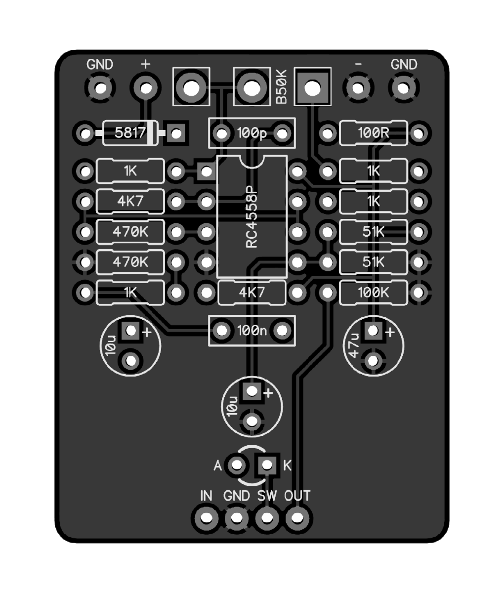
Alternatively the MXR Micro Amp can be a compact build, an op-amp boost. Alas, Robert's Micro Addition Boost is bigger and more complex than I think you want for this particular project — but you could build a Micro Amp on VERO or PERF.

You could catch a Tiger by the tail — another good op-amp boost that's compact, and in stock:

Thx! - If I get brave I’ll do it that way (jumper w vol pot on boost) and take the current vol pot off the board - or do the breakout board — The less desoldering the better for me currently- that’s when I cause problems or even mess up pcb’s , though I’m slowly getting better at desoldering ! I may end up using a sho boost, as I mostly like the tone , but still need to run more listening tests. This might be a good excuse to breadboard a few different types of boosts and listen to them. I just bought my first breadboard (Coppersound- expensive, but I didn’t want the headache of building & troubleshooting why the bb itself wasn’t working!)… I have to say, following their guides from right to left while I’m staring at a schematic that goes from left to right is not helping me (at all) trying to understand how schematics/electronics work 🙃🙃🙃
 
or do the breakout board

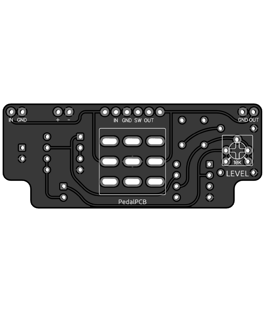
The breakout board is a fixed boost (it's adjustable internally, but intended to be set-and-forget) so if you go that route you'll want to leave the Equinox volume pot intact.

It is designed specifically for this task but I hate to play salesman (despite my shameless use of the "set it and forget it" catchphrase) so I didn't mention it.

:ROFLMAO:
👍- Using a 741 , does it sound like the mxr micro amp , or is it closer to something else?
 
That's what I thought. "Why didn't @Robert mention the Breakout Board With Output Boost?"
And no sooner had I thought that I realised two things:

1) Robert's modest and doesn't like to sound like a shill for his own stuff (so I stepped in);

and

2) Robert was embarrassed that he hadn't come up with a catchier name than "3PDT Breakout Board with Output Boost"


I get it though. He comes up with all those catchy names for other circuits, and just wants a rest, needs to take a break, and call the utility boards what they are. I mean, if I were looking for a 3PDT Breakout Board with Output Boost, I wouldn't necessarily type "BLACKBIRD AFTERBURNER BYPASS" into the search engine, it just wouldn't occur to me.

Maybe graphics would help...

BLACKBIRD AFTERBURNER BYPASS.jpg


When they were first developing the Blackbird engine, they tested it by running another jet-engine's exhaust into the Blackbird-engine's intake, to simulate the forced ram-air high-velocity intake it would experience at high-altitude — speeds of Mach 3+ and at altitudes of more than 80,000 feet.

Kind of like running a SHO into a Turbo Rat into a Triangle Muff...
 
Back
Top