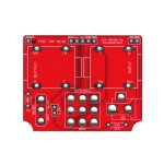
I recently came across this Effects Layouts Test Rig Mk III board in my pile (can't remember when I bought it  ) and when looking at it I realized I've never seen some of these labels before, particularly the pads where you connect the PCB you'd like to test. Can someone please help define these for this donkey? I emailed the dude from Effects Layouts and he never responded, so now I'm coming to you guys.
Forgive my ignorance. Even though I've built a ridiculous number of pedals, I again show myself for the charlatan that I am
See image below: SND, RTN...are these the same is "In" and "out"?
And what is L+ and L-?

Forgive my ignorance. Even though I've built a ridiculous number of pedals, I again show myself for the charlatan that I am
See image below: SND, RTN...are these the same is "In" and "out"?
And what is L+ and L-?


