The "Hortin FexDrive" circuit drew me in here... "
what the Fex is that?" ahh, I see — Fortin Hexdrive. Nice, fits with my lysdexia.
I didn't even realise there's a "
Stripboard Layouts" sub-forum, even though I now see I commented in one of its threads and have seen a couple other threads.
LOOKY-LOO on whatcha do done did...
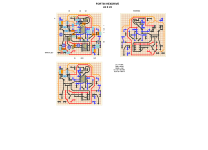
Technically nitpickin', that's a perf layout, not a stripboard layout. I prefer perf.
Are you working around a custom graphic?
If not, consider placing the pots in a more standard configuration — I like to use Robert's drill-templates so even though perf won't match his PCBs perfectly (he can lay out pots and switches in a way that's not locked into a perf-grid paradigm), I can get close enough that wiggling&bending the perf-mounted pots won't short anything out.
If you use regular pots mounted directly to your perf, it'll look a little something like this (pink rings for pots):
View attachment 111304
You could move the DRIVE to the right so it's even with TONE and then rotate the whole thang so you've got
________LEVEL
DRIVE _________TONE
Shifting the TONE a bit or what's around it would enable you to get rid of the jumper above TONE-3.
Your use of colour for the traces is inconsistent, which for me would lead to problems.
You've got black for ground, so it looks like your DRIVE is all connected to GND, and your OUT as well, looks like GND.
[EDIT: I mistook the GND-pad to the right of the BLUE OUT but, yeah, I got confused]
LVL looks like it has some power connected from lug 3 to the 1µF...
The more consistent and clear my layout is, the less likely I'll make mistakes on the build; I'd revise the colour-scheme on this one.
I'd use dark red for 9V+, for instance and then a bright red or pink or purple for half-voltage/doubled voltage etc to see what's going into the charge pump and what's coming out, and where it's all getting routed to.
Dave (Storyboardist) at Effects Layouts has provided much inspiration (not to mention some of the files/templates/components/etc for my perf layouts);
for instance, his 47µF electrolytics are larger than the 10µF electrolytic-caps to match real-world sizing. BTW, your 47µF has its legs spread wide, needlessly, as you're not running any trace between its legs, I'd adjust the layout to reflect the leg-spacing, though the physical circumference will be fine — but why not adjust it to visually match real-world dimensions? In future layouts you won't accidentally put components too close together that make if physically challenging to translate from the 2D to 3D.
See how ELS handles the power for the Fortin Boost:
Personally, for the 33 layout above, I'd spread out the LEVEL lugs at the bottom and board-mount the pot, then the perf isn't floating in the enclosure.
Oh, and I sort of try to put the 9v+ into the circuit where I think the DC jack is going to be (at the top, top-jacks etc), so yeah, give a mind to how things are going to go in the box, leave room for jacks/switches/future mods etc.
Hopefully my pedantic-puttering hasn't been too pestilent.
Happy Perfing!
Cheers,
FF
![HORTIN FEXDRIVE [FORTIN HEXDRIVE] perf layout djmiyta.png](https://pedalpcb-forum.nyc3.digitaloceanspaces.com/data/attachments/111/111324-b5d0c91b3221a1e2c9e4dba0f7077ab1.jpg?hash=1W-K_8gPNC "HORTIN FEXDRIVE [FORTIN HEXDRIVE] perf layout djmiyta.png")
