nshane
Member
Does anyone have a symbol/footprint for an illuminated 3PDT switch for KiCAD, or know where I can find one? Or where do I insert two pads for anode/cathode?
I am but a simple UV printer operator and I'm real new to this. I can't for the life of me figure out where the LED portion inserts into the schematic from looking at Tayda's datasheet and wiring diagram.
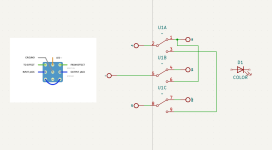
The above image is my current switch schematic in KiCAD with an LED just floating off in space.
I am but a simple UV printer operator and I'm real new to this. I can't for the life of me figure out where the LED portion inserts into the schematic from looking at Tayda's datasheet and wiring diagram.

The above image is my current switch schematic in KiCAD with an LED just floating off in space.
