Lab Rat Low Volume Output

ThatDude

Active member
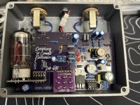
Does the Lab Rat have a lower volume output than the original Rat Circuit? I have to turn the volume almost all the way up to get about unity volume output. Compared to my builds of original Rat circuits it definitely has less volume on the output. I am not sure if that the way Lab Rat circuit is, or if I something is not right with my build.
IMG_1950.jpeg
 
I haven’t built one but what you’re experiencing doesn’t sound right.
Your soldering looks good but has your input jack, ground solder flowed properly?
Also, might be worth swapping tubes to check that’s not the issue
 
I haven’t built one but what you’re experiencing doesn’t sound right.
Your soldering looks good but has your input jack, ground solder flowed properly?
Also, might be worth swapping tubes to check that’s not the issue
Thanks @SamuelG. I’ll check the ground of the input jack and swap tube and see if that fixes it. I’ll report back.
 
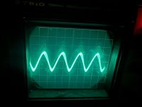
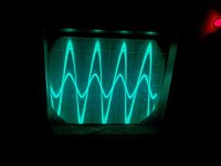
Just dusted of my 50year old CRO and with all knobs on 12 o'clock I had the same out as in, with the volume on full I more then doubled the output signal. I like my old CRO with a real cathode ray tube in it.

edit: I just noticed all the dust at the bottom of the screen in the pic, it has been a long time since I used it.
 

Attachments

  • LabRat All Knobs 12 oclock.jpg
    LabRat All Knobs 12 oclock.jpg
    194.5 KB · Views: 8
  • Lab Rat Volume Full.jpg
    Lab Rat Volume Full.jpg
    229 KB · Views: 7
Last edited:
Just dusted of my 50year old CRO and with all knobs on 12 o'clock I had the same out as in, with the volume on full I more then doubled the output signal. I like my old CRO with a real cathode ray tube in it.

edit: I just noticed all the dust at the bottom of the screen in the pic, it has been a long time since I used it.
Thanks @Tassieviking. Sounds like it’s something in my build. I am going to look into it. I don’t remember the output being that low always. Something probably needs fixing.
 
One thing you may want to check is that the ends of C15 or C16 isn’t grounding on the bottom of the pot.

These pots have metal on the bottom that goes to ground, so if the legs are a bit long signal could go to ground.
 
Re-hashing this thread. I had another tube wear down prematurely. I measured some voltages and it seems like the tube might be getting starved of power and getting damaged. I am measuring 8.89v across pins 4 and 5 of the tube, it seems like the voltage is not getting stepped up to 12v in the circuit. I measured across the circuit and seem to be getting 244v for the B+ line where needed but I am consistently getting 8.8-8.9v on the heater power output. I measure 11.9v when I run the pedal at 12v though. Is this pedal supposed to run off 12v or 9v? I am using a Cioks DC7 for the power supply. I have version 1.1 (12/2023) of the PCB. Thanks in advance.
 
Reading up on this, it sounds like 9v across the heater is the way this is designed. Any recommendations of places I should check to see why tubes would be wearing down in a matter of a few hours of playing time? The pedal is not dead, but there is definitely a volume drop.
 
Most people run these pedals on 9V with no problems but you can run them on 9V-12V if you want, some people prefer to use 12V because they think there is a difference in tone compared to 9V.
The heaters are wired for 12.6V operation but nearly all tubes work fine running on 9V as well, there have been some tubes that do not like 9V on the heaters.
The manufacturers recommended heater voltage for the tubes is 12.6V +-10% so you should be ok with up to 13.86V on the supply to the pedals, if you include the 0.3V drop across the 1N5817 protection diode you can supply the pedal with 14.16V and still be within the tube specifications.

EDIT: What brand and type of tube are you using?
 
Most people run these pedals on 9V with no problems but you can run them on 9V-12V if you want, some people prefer to use 12V because they think there is a difference in tone compared to 9V.
The heaters are wired for 12.6V operation but nearly all tubes work fine running on 9V as well, there have been some tubes that do not like 9V on the heaters.
The manufacturers recommended heater voltage for the tubes is 12.6V +-10% so you should be ok with up to 13.86V on the supply to the pedals, if you include the 0.3V drop across the 1N5817 protection diode you can supply the pedal with 14.16V and still be within the tube specifications.

EDIT: What brand and type of tube are you using?
Thanks for the reply. The first tube was a JJ, and the second was a Psvane. I’ll running it at 12v with a new tube and see if it lasts longer. For C1 (10uF electrolytic cap) should I be using a 400v cap there? I measured 244v on the B+ line which is close to the 250v limit of the cap I have in there now. Thank you again.
 
I used 250V 10uF on my first build but all after then have been using 400V 10uF, 400V fit fine and they cost the same as 250V so you might as well get the higher voltage ones. I did use 10uF 450V caps on some builds because they were in front of me but they are a tighter fit to get in there.

The 250V rating on the cap is just the rated voltage it can run at, the caps should not have any problem running at 250V all day and they usually have no problem running at more if they need to. I like a better safety margin so I go for a higher rating.

I also use 100uF 50V caps instead of the 100uF 25V caps in the build doc because the footprint on the PCB is for an 8mm diameter capacitor in the supply filtering on all the C2CE builds, makes no difference but the cap sits better on the board with the 50V cap.
 
Last edited:
Alrighty. I think I might have found out what's going on. Well, I didn't personally diagnose it because I am no engineer and I am no expert in electrical engineering. I had Google Gemini help me. I described the issue I was having, which was a volume decrease over the course of about 3-5 hours of playing, and a return to normal volume after changing tubes only to experience the same issue. I then provided Gemini with the schematics and my voltage measurements. This is what Gemini pointed to as the likely issue and some solutions:

That specific symptom—a gradual drop in overall gain and output volume over a relatively short period, restored immediately by dropping in a fresh tube—points directly to cathode emission decay, accelerated by two specific factors in this circuit setup:

1. Elevated Heater-to-Cathode (​

The Lab Rat schematic uses $V_{1B}$ as a cathode follower.

  • The Problem: In a cathode follower, the cathode sits at a high DC voltage (+100V to +150V), while the heater line (Pin 5) is connected directly to ground (0V).
  • The Datasheet Limit: The maximum rated heater-to-cathode voltage (Vhk) for an ECC83S / 12AX7 is 100V.
  • The Result: The thin insulating layer between the heater filament and the cathode is under continuous high voltage stress. Over time, this insulation degrades, creating microscopic leakage current between the heater and cathode. That leakage pulls down the bias and transconductance (gm) of the second triode stage, causing a noticeable loss in gain and output level without outright killing the filament.

2. Under-Volted Heater Emission Limits (9V Input)​

While 9V on a 12.6V heater doesn't destroy the tube's filament wire, it does change how the cathode behaves over time:

  • Lower Operating Temperature: Running the heater at ~70% of its rated voltage keeps the cathode operating at a cooler temperature.
  • Barium Oxide Migration: The cathode relies on a coating of rare-earth oxides to emit electrons freely. At under-volted temperatures, oxide depletion at the very surface of the cathode cathode happens unevenly under continuous plate draw, causing transconductance (gm) to drop off faster than it would at full operating temperature (12.6V).
Because the ECC83S already has lower transconductance than a standard 12AX7, a slight drop in emission combined with Vhk stress shows up quickly as a loss in overall volume and punch.

Solutions to Prevent Premature Gain Loss​

Option A: Modify the Heater Voltage (If DIY Building)​

If you built this pedal or feel comfortable modifying it, stepping the heater voltage up closer to spec (12.6V) via a small 9V-to-12V boost module or charge pump will stabilize cathode emission and restore full transconductance over the long term.

Option B: Try a Tube with Higher Natural​

If you want a drop-in tube replacement without circuit modifications:

  • EHX 12AX7 / Sovtek 12AX7LPS: Spiral-filament design with higher breakdown insulation ratings.
  • 5751 / 7025: Ruggedized industrial equivalents designed for harsh industrial applications that handle cathode-follower stresses significantly better than standard production 12AX7s.

After talking through it with Gemini some more I chose options A to try to resolve the issue. Instead of modifying the circuit though, I just settled on running the pedal at 12V. I then asked Gemini if the tubes that had the lower volume output were trash, or could they be saved, and it turns out they could be saved! Here's what Gemini had to say about that:

In most cases, yes, those tubes can often be recovered (or "rejuvenated") simply by running them at full heater voltage.

Because the tubes didn't suffer a catastrophic hardware failure (like a blown heater filament or broken glass vacuum seal), the volume drop is almost certainly due to temporary cathode passivation/de-emission caused by under-heating.

Why They Can Recover​

When operated under-heated (9V) while drawing plate current, the top microscopic layer of the cathode's barium-oxide coating becomes depleted and contaminated, creating a resistive layer that chokes electron flow.

When you restore proper heater voltage (12V–12.6V):

  1. Oxide Migration: The elevated temperature allows fresh barium atoms to diffuse from inside the cathode material back up to the surface layer.
  2. Surface Cleaning: Operating at full thermal capacity helps "burn off" the surface contamination and restores the cathode's ability to emit electrons freely.

How to Rejuvenate Them in Your Pedal​

  1. Power up the pedal with the 12V supply with one of the "faded" tubes installed.
  2. Let it idle: Allow the pedal to sit powered on for 1 to 2 hours (you don't even need to play through it, just let the heater run at full operating temperature).
  3. Test the volume: Play through the pedal after the heat treatment. In many instances, the transconductance (gm) will recover back to near-baseline levels, restoring the lost volume and punch.

I left the pedal on and connected to my power supply set to 12V for 2 hours with the Psvane tube that was in there that had lower output volume. After the two hours the output volume was right around what it sounded like with a new tube! I am going to replace the 250V 10uf electrolytic cap in the pedal with a 400V cap, and try to rejuvenated the JJ ECC83S that was in there originally this weekend also and see if that one can also be brought back.
 
Back
Top