falco_femoralis
Well-known member
Hi all, I finally had some good weather to clear coat some projects I started over the winter. Here is my build of a PCB 037. This board has the option to use either silicon diodes or LEDs for the clipping section so I wanted to utilize both via a switch.
Here is the board built sans the clipping diodes

Here is a shot of how I mounted the diode array. I haven't installed the return wire yet, which will go into the K solder pad at the top

Installed into the enclosure

Here I have the audio jacks and footswitch installed. I love the footswitch daughterboards. I'm now wiring up the diode switch. This will also control the indicator LED

Everything is in except the indicator LED

Doing the wiring for the LED. I tin both the LED legs and the wires, use flux to mate them together easily, and heat shrink the exposed leads

And everything is done. I bend the leads for the LED at a right angle and hot glue it to the underside of the PCB. I love hot glue

Here is a profile of the toggle switch. I bought a couple short bat type and I figured this was the best use of that style.

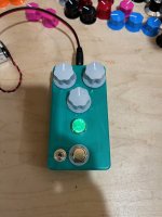
And we're done!

It even works, as a bonus! This is with the silicon diodes selected

And this is with the LED clipping diodes in the circuit instead

I love the green color of the enclosure, but I am a bit bummed by the color of the LED. It is just a bit too yellow in person and doesn't quite match the enclosure color. And I'd like to use red for the LED indicator rather than blue, but it really didn't look good with the green jewel. I may try a white jewel, then use the green and blue of the tri-color LED together to get more of a teal color, and then the red can be for the LED section.
The pedal sounds fine, I definitely like the silicon sound more than the LED, but I'm glad I tried it out.
Next on the block is probably a Resinite Overdrive, as soon as a set of knobs comes in the mail
Here is the board built sans the clipping diodes

Here is a shot of how I mounted the diode array. I haven't installed the return wire yet, which will go into the K solder pad at the top

Installed into the enclosure

Here I have the audio jacks and footswitch installed. I love the footswitch daughterboards. I'm now wiring up the diode switch. This will also control the indicator LED

Everything is in except the indicator LED

Doing the wiring for the LED. I tin both the LED legs and the wires, use flux to mate them together easily, and heat shrink the exposed leads

And everything is done. I bend the leads for the LED at a right angle and hot glue it to the underside of the PCB. I love hot glue

Here is a profile of the toggle switch. I bought a couple short bat type and I figured this was the best use of that style.

And we're done!

It even works, as a bonus! This is with the silicon diodes selected

And this is with the LED clipping diodes in the circuit instead

I love the green color of the enclosure, but I am a bit bummed by the color of the LED. It is just a bit too yellow in person and doesn't quite match the enclosure color. And I'd like to use red for the LED indicator rather than blue, but it really didn't look good with the green jewel. I may try a white jewel, then use the green and blue of the tri-color LED together to get more of a teal color, and then the red can be for the LED section.
The pedal sounds fine, I definitely like the silicon sound more than the LED, but I'm glad I tried it out.
Next on the block is probably a Resinite Overdrive, as soon as a set of knobs comes in the mail
Last edited:
