laundryman
Member
Hi,
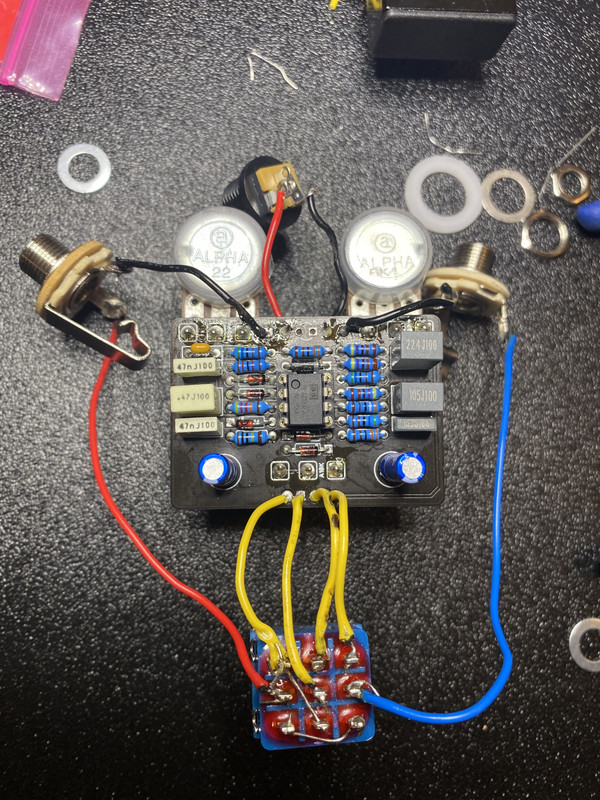
I finished up a Mach 1 PCB tonight and am having some troubleshooting issues. When powered, the LED does come on. True bypass does pass through the cables and to my amp. However when stomped on, all sound cuts. I have checked for any grounding out and have tried it both outside and inside an enclosure. I tried swapping the OPA2134 IC with a TL072, but had the same issue.
Below are several photos of my (sloppy) build. Forgive the very shoddy job - I'm still learning the art of this ha.
I took several photos so I linked them to an album here, instead of having 14 photos spam several screen scrolls.
Edit: here are additional photos of it outside of the case after trying a new switch and without a breakout board; disregard the power jack not being soldered in these photos; it's only because I had just taken it out of the case.
Any help would be great.
Thanks!
Last edited: