Tremster
Member
Dear forum,
I don't feel confident enough with my diagram reading skills, any help would be appreciated.
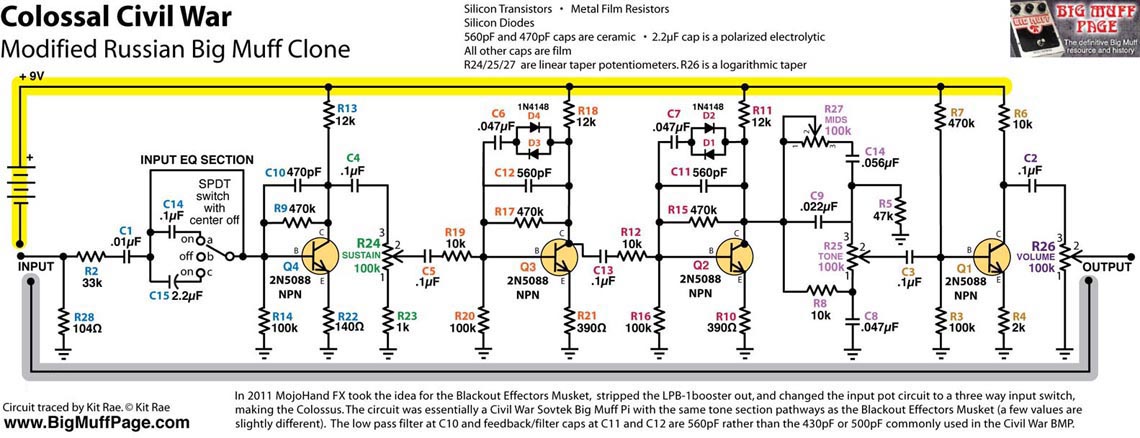
A friend asked me to build a Mojo Hand Colossus (=a variant of a Russian Muff with mids control and an input cap switch), he had an original years ago.
I can't find a PCB for it, but I have a Fuzzdog BMP board that should do fine: https://shop.pedalparts.co.uk/Big_Muff_Pi/p847124_20010593.aspx
The schematic is in the BOM on page 3: http://pedalparts.co.uk/docs/BMP2018.pdf
The Colossus schematic is on the Kit Rae Muff page: http://www.bigmuffpage.com/Big_Muff_Pi_versions_schematics_part4.html:

The question is (parts numbers are different):
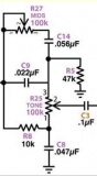
How do I match this bit from the Kit Rae schematic
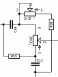
with this bit from the Fuzzdog schematic
Where does Kit Rae's C14 go on the PCB??
Kit Rae's C9 is parallel to the Mids pot, Fuzzdog's C10 is before the pot??
The Colossus uses much larger values around the Mids pot than other Muffs with a Mids pot (Musket, Hoof; see Fuzzdog doc for those). Is there something wrong?
This is beyond me, I'm sorry.
Thank you!!!!
Here's what I came up with matching the Kit Rae diagram with the Fuzzdog diagram for use on the PCB (The parts numbers are for the PCB, Kit Rae has different numbers). I think I have it all except for the parts around the Mids knob parts mentioned above:
R1 33k
R2 100k
R3 470k
R4 140R
R5 12k
R7 1k
R8 10k
R9 100k
R10 470k
R11 12k
R12 390R
R13 10k
R14 390R
R15 470k
R16 100k
R17 12k
R18 47k ??
R19 10k ??
R21 100k
R22 470k
R23 2k
R24 10k
R25 1M
(no R6 and R20 on PCB)
C1 10nF + 100nF/2u2 on switch
C2 470pF
C3 100nF
C4 100nF
C5 560pF
C6 47nF
C7 100nF
C8 560pF
C9 47nF
C10 22nF ??
C11 47nF ??
C12 100nF
C13 100nF
C14 100uF
D1-2/4-5 1N4148
D3&6 by choice
D7 1N4001
Q1-4 2N5088
Tone / Mids / Sustain 100kB
Volume 100kA
I don't feel confident enough with my diagram reading skills, any help would be appreciated.
A friend asked me to build a Mojo Hand Colossus (=a variant of a Russian Muff with mids control and an input cap switch), he had an original years ago.
I can't find a PCB for it, but I have a Fuzzdog BMP board that should do fine: https://shop.pedalparts.co.uk/Big_Muff_Pi/p847124_20010593.aspx
The schematic is in the BOM on page 3: http://pedalparts.co.uk/docs/BMP2018.pdf
The Colossus schematic is on the Kit Rae Muff page: http://www.bigmuffpage.com/Big_Muff_Pi_versions_schematics_part4.html:
The question is (parts numbers are different):
How do I match this bit from the Kit Rae schematic
with this bit from the Fuzzdog schematic
Where does Kit Rae's C14 go on the PCB??
Kit Rae's C9 is parallel to the Mids pot, Fuzzdog's C10 is before the pot??
The Colossus uses much larger values around the Mids pot than other Muffs with a Mids pot (Musket, Hoof; see Fuzzdog doc for those). Is there something wrong?
This is beyond me, I'm sorry.
Thank you!!!!
Here's what I came up with matching the Kit Rae diagram with the Fuzzdog diagram for use on the PCB (The parts numbers are for the PCB, Kit Rae has different numbers). I think I have it all except for the parts around the Mids knob parts mentioned above:
R1 33k
R2 100k
R3 470k
R4 140R
R5 12k
R7 1k
R8 10k
R9 100k
R10 470k
R11 12k
R12 390R
R13 10k
R14 390R
R15 470k
R16 100k
R17 12k
R18 47k ??
R19 10k ??
R21 100k
R22 470k
R23 2k
R24 10k
R25 1M
(no R6 and R20 on PCB)
C1 10nF + 100nF/2u2 on switch
C2 470pF
C3 100nF
C4 100nF
C5 560pF
C6 47nF
C7 100nF
C8 560pF
C9 47nF
C10 22nF ??
C11 47nF ??
C12 100nF
C13 100nF
C14 100uF
D1-2/4-5 1N4148
D3&6 by choice
D7 1N4001
Q1-4 2N5088
Tone / Mids / Sustain 100kB
Volume 100kA
Last edited: